Download PDF
Download page Cross Section Interpolation.
Cross Section Interpolation
Occasionally it is necessary to supplement surveyed cross section data by interpolating cross sections between two surveyed sections. Interpolated cross sections are often required when the change in velocity head is too large to accurately determine the change in the energy gradient. An adequate depiction of the change in energy gradient is necessary to accurately model friction losses as well as contraction and expansion losses. When cross sections are spaced too far apart, the program may end up defaulting to critical depth.
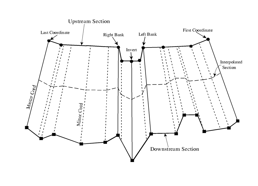
The HEC-RAS program has the ability to generate cross sections by interpolating the geometry between two user entered cross sections. The geometric interpolation routines in HEC-RAS are based on a string model, as shown in the figure below.
The string model in HEC-RAS consists of cords that connect the coordinates of the upstream and downstream cross sections. The cords are classified as "Master Cords" and "Minor Cords." The master cords are defined explicitly as to the number and starting and ending location of each cord. The default number of master cords is five. The five default master cords are based on the following location criteria:
- First coordinate of the cross section (May be equal to left bank).
- Left bank of main channel (Required to be a master cord).
- Minimum elevation point in the main channel.
- Right bank of main channel (Required to be a master cord).
- Last coordinate of the cross section (May be equal to right bank).
The interpolation routines are not restricted to a set number of master cords. At a minimum, there must be two master cords, but there is no maximum. Additional master cords can be added by the user. This is explained in "Modeling Culverts" of the HEC-RAS user's manual, under cross section interpolation.
The minor cords are generated automatically by the interpolation routines. A minor cord is generated by taking an existing coordinate in either the upstream or downstream section and establishing a corresponding coordinate at the opposite cross section by either matching an existing coordinate or interpolating one. The station value at the opposite cross section is determined by computing the proportional distance that the known coordinate represents between master chords, and then applying the proportion to the distance between master cords of the opposite section. The number of minor cords will be equal to the sum of all the coordinates in the upstream and downstream sections minus the number of master cords.
Once all the minor cords are computed, the routines can then interpolate any number of sections between the two known cross sections. Interpolation is accomplished by linearly interpolating between the elevations at the ends of a cord. Interpolated points are generated at all of the minor and master cords. The elevation of a particular point is computed by distance weighting, which is based on how far the interpolated cross section is from the user known cross sections.
The interpolation routines will also interpolate roughness coefficients (Manning's n). Interpolated cross section roughness is based on a string model similar to the one used for geometry. Cords are used to connect the breaks in roughness coefficients of the upstream and downstream sections. The cords are also classified as master and minor cords. The default number of master cords is set to four, and are located based on the following criteria:
- First coordinate of the cross section (may be equal to left bank).
- Left bank of main channel.
- Right bank of main channel.
- Last coordinate of the cross section (may be equal to right bank).
When either of the two cross sections has more than three n values, additional minor cords are added at all other n value break points. Interpolation of roughness coefficients is then accomplished in the same manner as the geometry interpolation.
In addition to the Manning's n values, the following information is interpolated automatically for each generated cross section: downstream reach lengths; main channel bank stations; contraction and expansion coefficients; normal ineffective flow areas; levees; and normal blocked obstructions. Ineffective flow areas, levees, and blocked obstructions are only interpolated if both of the user-entered cross sections have these features turned on.
Cross section interpolation is accomplished from the user interface. To learn how to perform the interpolation, review the section on interpolating in "Modeling Culverts" of the HEC-RAS user's manual.