Download PDF
Download page Flow Distribution Calculations.
Flow Distribution Calculations
The general 1D cross section output shows the distribution of flow in three subdivisions of the cross section: left overbank, main channel, and the right overbank. Additional output, showing the distribution of flow for multiple subdivisions of the left and right overbanks, as well as the main channel, can be requested by the user.
The flow distribution output can be obtained by first defining the locations that the user would like to have this type of output. The user can either select specific locations or all locations in the model. Next, the number of slices for the flow distribution computations must be defined for the left overbank, main channel, and the right overbank. The user can define up to 45 total slices. Each flow element (left overbank, main channel, and right overbank) must have at least one slice. The user can change the number of slices used at each of the cross sections. The final step is to perform the normal profile calculations. During the computations, at each cross section where flow distribution is requested, the program will calculate the flow (discharge), area, wetted perimeter, percentage of conveyance, hydraulic depth, and average velocity for each of the user defined slices. For further details on how to request and view flow distribution output, see "Modeling Multiple Bridge and/or Culvert Openings" and "Modeling Gated Spillways, Weirs and Drop Structures" of the HEC-RAS User's manual.
The computations for the flow distribution are performed after the program has calculated a water surface elevation and energy by the normal methodology described in "Theoretical Basis for One-Dimensional and Two-Dimensional Hydrodynamic Calculations" of this manual. The flow distribution computations are performed as follows:
- First, the water surface is computed in the normal manner of using the three flow subdivisions (left overbank, main channel, and right overbank), and balancing the energy equation.
- Once a water surface elevation is computed, the program slices the cross section into the user defined flow distribution slices, and then computes an area, wetted perimeter, and hydraulic depth (area over top width) for each slice.
- Using the originally computed energy slope ( Sf ), the cross section Manning's n values, the computed area and wetted perimeter for each slice, and Manning's equation, the program computes the conveyance and percentage of discharge for each of the slices.
- The program sums up the computed conveyance for each of the slices. In general, the slice computed conveyance will not be the same as the originally computed conveyance (from the traditional methods for conveyance subdivision described in "Theoretical Basis for One-Dimensional and Two-Dimensional Hydrodynamic Calculations" of this manual). Normally, as a cross section is subdivided further and further, the computed conveyance, for a given water surface elevation, will increase.
- In order to correct for the difference in computed conveyances, the program computes a ratio of the original total conveyance (from the normal calculations) divided by the total slice conveyance. This ratio is then applied to each of the slices, in order to achieve the same conveyance as was originally computed.
- The final step is to compute an average velocity for each slice. The average velocity is computed by taking the discharge and dividing by the area for each of the user defined slices.
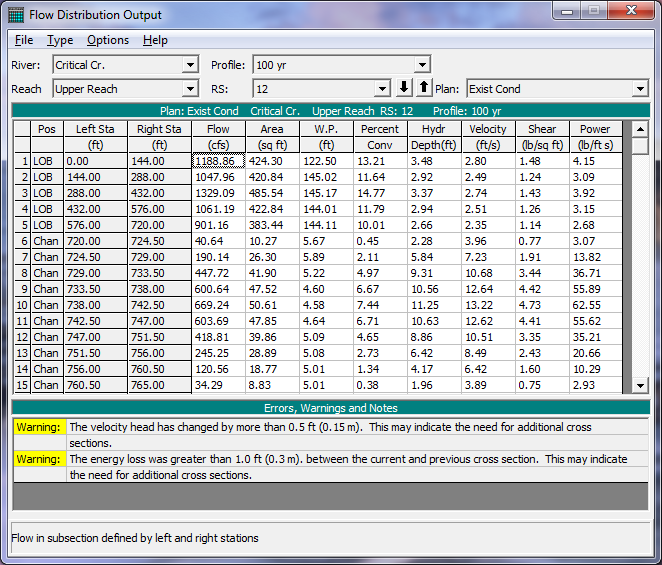
An example of the flow distribution output is shown in the figure below.
In general, the results of the flow distribution computations should be used cautiously. Specifically, the velocities and percentages of discharge are based on the results of a one-dimensional hydraulic model. A true velocity and flow distribution varies vertically as well as horizontally. To achieve such detail, the user would need to use a three-dimensional hydraulic model, or go out and measure the flow distribution in the field. While the results for the flow distribution, provided by HEC-RAS, are better than the standard three subdivisions (left overbank, main channel, and right overbank) provided by the model, the values are still based on average estimates of the one-dimensional results. Also, the results obtained from the flow distribution option can vary with the number of slices used for the computations. In general, it is better to use as few slices as possible.