Download PDF
Download page Pressurized Pipe Flow.
Pressurized Pipe Flow
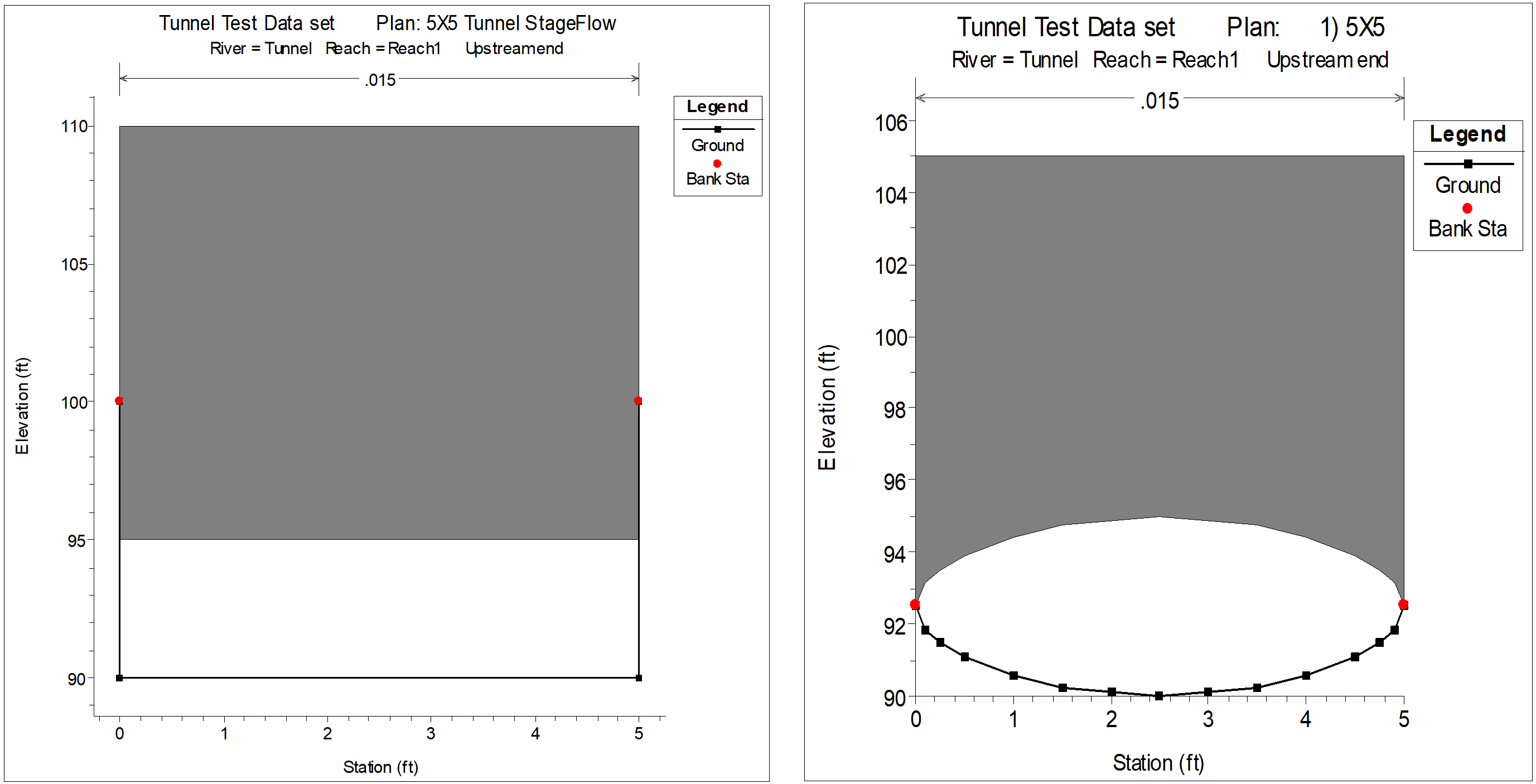
HEC-RAS has the ability to model pressurized pipe flow for both 1D steady flow and unsteady flow analyses (Only the 1D Finite Difference unsteady flow solution, not the 1D Finite Volume). Pipes (other than culverts through a roadway, which are handled with the culvert hydraulics routines) can be modeled by using cross sections (to represent the bottom half of the pipe/tunnel) with the Lid option to represent the top of the pipe. An example plot of cross sections with a lid is shown in the figure below. 
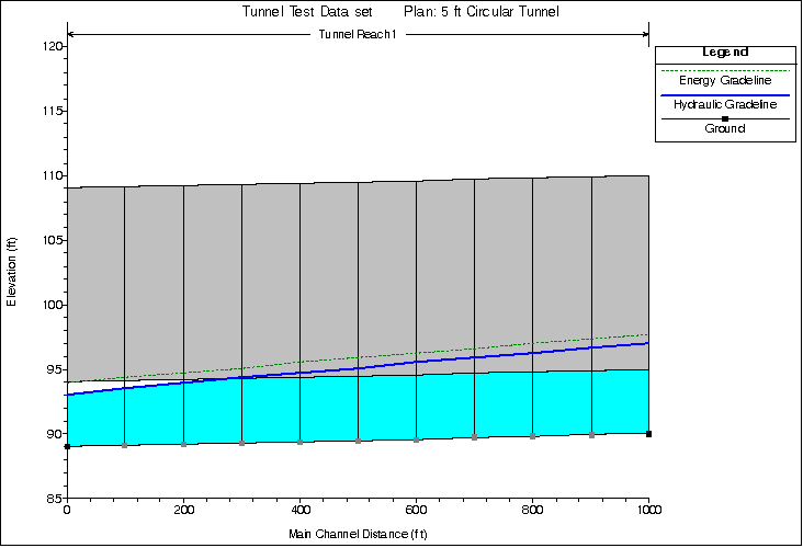
Steady Flow Hydraulics. For a steady flow analyses the program solves the energy equation, just as it normally would for any cross section. The only difference is that the area and wetted perimeter are limited to the open area between the cross section bottom and lid. When the program computes a water surface greater than the top of the open conduit, the water surface line is representative of the hydraulic gradeline. The flow area and wetted perimeter are still being computed from the available open area, but the balance of the energy equation requires the computation to use the hydraulic gradeline instead of the water surface elevation in order to achieve a balance of energy. An example of this is shown in the figure below. 
For steady flow hydraulics, the user is not required to turn on any special option to get this to work. Just simply add the lid to any cross sections and this will happen when the energy equation is solved. Note: If the user does not make the top of the lid high enough, and the hydraulic gradeline (water surface elevation) goes above the top of the lid, the program will use the area above the lid as available flow area.
Unsteady Flow Hydraulics. For unsteady flow hydraulic computations, the modeling of pressurized conduit flow requires the use of Priessmann Slot theory. Closed conduits can experience both open channel flow and pressure flow within the same pipe. Generally, pressure flow is most often analyzed using waterhammer equations, which are presented below for a circular pipe (Streeter and Wylie, 1979).
Momentum:
| 1) | \displaystyle V \frac{\delta V}{\delta x} + \frac{\delta V}{\delta t} + \frac{1}{\rho} \frac{\delta h}{\delta x} + gsin \theta + \frac{fV|V|}{2D} =0 |
Continuity:
| 2) | \displaystyle \frac{1}{\rho} \left( V \frac{\delta h}{\delta x} + \frac{\delta h}{\delta t} \right) + a^2 \frac{\delta V}{\delta x} =0 |
| Symbol | Description | Units |
|---|---|---|
V | velocity | |
h | piezometric head | |
\rho | fluid density | |
g | gravity | |
\theta | bed slope | |
f | Darcy-Weisbach friction factor | |
D | Pipe diameter | |
t | time | |
x | distance |
These hyperbolic partial differential equations describe the translation of pressure waves through an elastic medium. Impulses travel at a rate given by the characteristic directions:
| 3) | \displaystyle \frac{dx}{dt} = V \pm a |
Because the wave celerity a is on the order of 1000 times larger than the water velocity V, the advective terms in (1) and (2) are often dropped and the characteristic directions become (Streeter and Wylie, 1979):
| 4) | \displaystyle \frac{dx}{dt} = \pm a |
For pressure flow, the celerity of an acoustic wave (sound wave) with a correction for elasticity of the conduit material is:
| 5) | \displaystyle a = \left[ \frac{\gamma}{g} \left( \frac{1}{K} + \frac{Dc_1}{Ee} \right) \right] ^{-0.5} |
| Symbol | Description | Units |
|---|---|---|
\gamma | specific weight of water | |
K | bulk modulus of elasticity of water | |
D | conduit diameter | |
e | conduit thickness | |
c_1 | conduit support parameter, typically 0.91 | |
E | Young's modulus of elasticity |
If the conduit is buried or bored through rock, e is large and the elasticity correction becomes insignificant, hence:
| 6) | \displaystyle a = \left( g \frac{K}{\gamma} \right) ^{0.5} |
If the bulk modulus of elasticity K is 43.2 x 10⁶ lbs/ft2, then the celerity a = 4721 ft/s.
The shallow water equations, can be written using velocity V and depth h as the dependent variables.
Momentum:
| 7) | \displaystyle \frac{\delta V}{\delta t} + V \frac{\delta V}{\delta x} + g \frac{\delta h}{\delta x} +g(S_f - S_0)=0 |
Continuity:
| 8) | \displaystyle T_w \frac{\delta h}{\delta t} + VT_w \frac{\delta h}{\delta x} +A \frac{\delta V}{\delta x} =0 |
Where: A=the cross-sectional areaTw=Top width of the flow
Like the water hammer equations, these equations are hyperbolic partial differential equations for which the impulses travel at a rate given by characteristic directions:
| 9) | \displaystyle \frac{dx}{dt} =V \pm c |
In the above equation, c is the celerity of a gravity wave. The celerity of a gravity wave is:
| 10) | c = \sqrt{gD} |
| Symbol | Description | Units |
|---|---|---|
c | the wave celerity | |
D | the hydraulic depth | A/Tw |
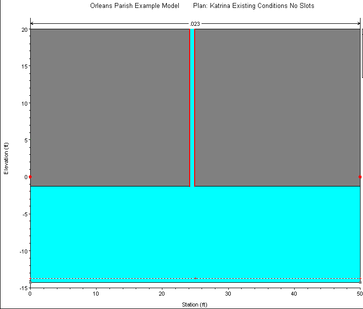
(6) and (10) are identical except for the values of the wave celerities. Recognizing this fact, Priessmann (Cunge et al., 1980) suggested that pressure waves can be approximated by the shallow water equations if the celerity c is set to the acoustic celerity. Priessmann proposed the insertion of a slot of constant width and infinite height above the top of the conduit (see figure below). 
The width of the slot is determined by equating the wave celerity of a gravity wave (10) to the acoustic wave celerity (6) and solving for the top width:
| 11) | \displaystyle T_w = \frac{A \gamma}{K} |
In which A is the full flow area of the pipe (not including the slot). Thus the wave celerity of a gravity wave , when the water surface is in the slot, is equivalent to that of an acoustic wave. The procedure has great utility in that both open channel flow and pressure flow can be solved with the same equation set in the same model. The penalty in accuracy is a very slight attenuation due to the increase in area associated with the slot. However, because the total slot area at a head of 200 ft is 2.98 x 10⁻⁴ times the area, the increase in storage is negligible.
Within HEC-RAS the user can model any shape of pipe by entering the bottom half as a cross section and the top half as the lid. The Priessmann slot method is an option that must be turned on for each cross section that has a lid. To learn how to turn this option on in the User Interface, please review the section called "Modeling Pressurized Pipe Flow" in "Modeling Culverts" of the HEC-RAS User's manual.
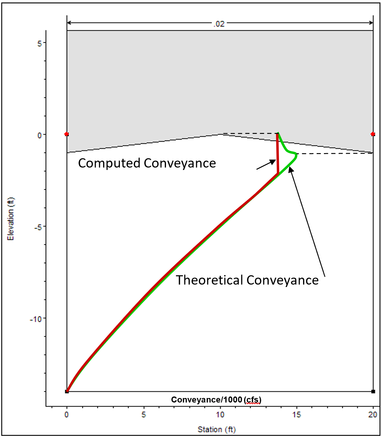
During the unsteady flow calculations, as flow transitions from open channel flow to pressure flow, there can be a significant drop in conveyance as the water hits the top of the pipe and pressurizes. This is due to the large increase in wetted perimeter (friction) with little increase in flow area. Thus, the computed conveyance will drop as the water hits the top of the pipe. This drop in conveyance can cause an instability in the numerical solution as flow transitions from open channel flow to pressure flow. Because of this, the conveyance curves computed by HEC-RAS are cut off at the conveyance associated with a full flowing pipe, rather than going up to the theoretical maximum conveyance (right before the pipe pressurizes) and then coming back down to the full flowing pipe value (see figure below). 