Download PDF
Download page Mixed Flow Analysis - Example 9.
Mixed Flow Analysis - Example 9
This example demonstrates the analysis of a river reach that contains both subcritical and supercritical flow. This mixed flow problem is caused by a bridge structure that constricts the flow enough to force it to pass through critical depth, creating a backwater effect and causing subcritical flow immediately upstream from the bridge.
The discussion of this example will focus on the analysis of the mixed flow regime. Additionally, the bridge structure was analyzed using both the energy method and the pressure flow method. The results of these methods are then compared. For a more detailed discussion on bridge analyses, the user is referred to Chapter 6 of the User's Manual and to Chapter 5 of the Hydraulic Reference Manual.
To review the data files for this example, from the main HEC-RAS window, select File and then Open Project. Go to the directory in which you have installed the HEC-RAS example data sets. From the "Applications Guide\Example 9 – Mixed Flow Analysis" subdirectory, select the project labeled "Mixed Flow - Example 9." This will open the project and activate the following files:
Plan: "Putah Creek Bridge - Energy"
Geometry:"Base Geometry Data - Energy"
Flow: "100 Year Discharge"
 Example 9 - Mixed Flow Analysis.zip
Geometric Data
The geometric data for this example consists of the river system schematic, the cross section data, the locations of the cross sections, and the bridge data. Each of these components is discussed below.
River System Schematic
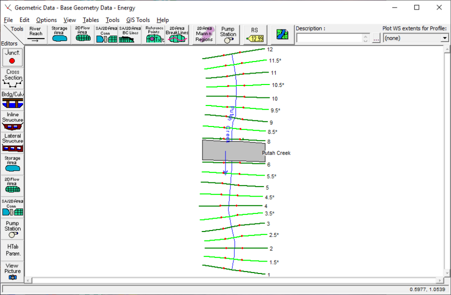
To view the river system schematic, from the main program window select Edit and then Geometric Data. This will activate the Geometric Data Editor and display the schematic, as shown in the figure below. The schematic shows the layout of a section of Putah Creek, which consists of 20 cross sections. Cross section 12 is the upstream river station and cross section 1 is the downstream river station. Additionally, a bridge was located at river station 7 and will be discussed in a subsequent section.
Cross Section Data
The data for each cross section is comprised of: a description, the X-Y coordinates, downstream reach lengths, Manning's n values, main channel bank stations, and the expansion and contraction coefficients. The data used for this example can be viewed by selecting the Cross Section icon on the Geometric Data Editor (above). It should be noted that the whole number cross sections were obtained from field data and the cross sections with an * were interpolated. This will be discussed in the following section.
Location of the Cross Sections
The location of the cross sections in relation to the bridge is crucial for the accurate calculation of the expansion and contraction losses. The bridge routine utilizes four cross sections, two upstream and two downstream from the structure, to determine the energy losses through the structure. The modeler is referred to chapter 6 of the User's Manual and chapter 5 of the Hydraulic Reference Manual for additional discussion on the location of cross sections and for modeling bridges.
For this example, the flow used for this analysis will remain in the main channel during the event. Additionally, there is only one pier for the bridge and the cross sections in the vicinity of the bridge do not reflect major changes in geometry. Therefore, there is no major expansion or contraction losses occurring in the vicinity of the bridge.
Since the flow in the main channel is supercritical, the cross sections were placed close together to more accurately calculate the energy losses along the channel. The cross-section data from the field survey were 100 feet apart. These data were entered and then additional cross sections were interpolated at 50 feet intervals. This was performed from within the Geometric Data Editor by selecting Tools, XS Interpolation, and then Within a Reach. This activated the XS Interpolation by Reach Window as shown in the figure below.
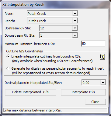
To perform the interpolation, the reach of Putah Creek and the starting and ending river stations of 12 and 1 were selected as shown in the figure above. Then, a maximum distance of 50 feet was entered and the Interpolate XS's button was selected. This created the interpolated cross sections along the entire river reach. After the interpolation, each interpolated cross section was reviewed to determine the adequacy of the interpolation. For additional discussion on cross section interpolation, the user is referred to chapter 6 of the User's Manual and to chapter 4 of the Hydraulic Reference Manual.
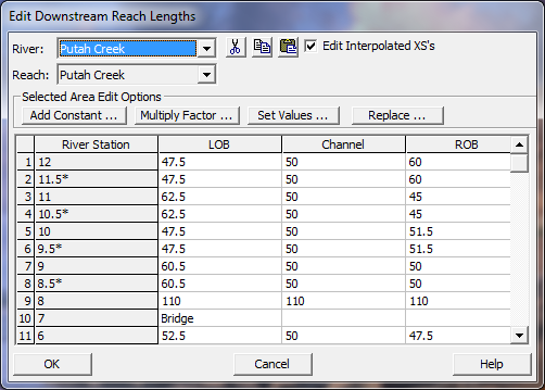
As a final review of the cross section locations, from the Geometric Data Editor select Tables and then Reach Lengths. This will activate the Reach Lengths Table as shown in the figure below. As can be seen in the table, the final channel reach lengths are 50 feet for each cross section, except through the bridge.
Bridge Data
To enter the bridge data for this example, first the deck/roadway data, then the pier data, and finally the bridge modeling approach data were entered. These components are described in the following sections.
Deck/Roadway Data. From the Geometric Data Editor, select the Bridge/Culvert icon. This will activate the Bridge/Culvert Data Window. Then select the Deck/Roadway icon on the left side of the window. This will activate the Deck/Roadway Data Editor as shown in the figure below.
As shown in the figure below, the first item on the top row of the editor is the distance from the river station immediately upstream of the bridge (river station 8) to the upstream side of the bridge. For this example, this distance was set at 10 feet. The next item is the width of the deck/roadway and this distance was 90 feet. The program will then add the 10 feet and the 90 feet to obtain 100 feet as the distance from the river station 8 to the downstream side of the bridge. From the Reach Lengths Table, it can be seen that the distance from river station 8 to river station 6 was 110 feet. Therefore, the program will allow for 10 feet of distance from the downstream side of the bridge to river station 6 (the river station located immediately downstream of the bridge). The last item on the top row of the editor is the weir coefficient, which was set at 2.9.
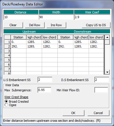
The central portion of the editor consists of the station and elevation data for the low and high cords of the deck/roadway. These values were entered as shown. Finally, the bottom portion of the editor consists of the data entry for the weir flow calculations. For this example, weir flow did not occur and this data will not be emphasized. For additional discussion on the deck/roadway data, the user is referred to example 2 for bridges and to example 3 for culverts. The OK button was then selected to exit the editor.
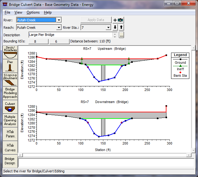
Pier Data. To enter the pier data, the Pier icon was selected from the Bridge/Culvert Data Editor. This activated the Pier Data Editor. For this example, the bridge geometry consisted of only one pier located at a centerline station of 150 and a width of 8 feet. This data was entered and then the editor was closed. This concluded the input of the bridge geometry and the bridge appeared in the Bridge/Culvert Data Editor as shown in the figure below.
As a final note for the bridge geometry, there were no ineffective flow areas defined for the analysis. This was due to the fact that the flow for the analysis remained in the main channel and the bridge geometry did not create any appreciable ineffective flow areas. This will become more apparent during the review of the output.
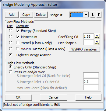
Bridge Modeling Approach. The final component of the geometric data is the entering of the coefficients for the bridge analysis. This was performed by selecting the Bridge Modeling Approach icon on the Bridge/Culvert Data Editor. This activated the Bridge Modeling Approach Editor as shown in the figure below.
The first selection is the low flow computation methods. For this example, the energy and momentum methods were selected. Then, the Highest Energy Answer field was selected. This will inform the program to use the greater answer of the energy and the momentum methods for the final solution of the low flow analysis. The next selection was the method for the high flow analysis. For this simulation, the energy method was selected. (A subsequent analysis was performed with the pressure/weir method and will be discussed later.)
This concluded the geometric input for the analysis and the data was then saved as "Base Geometry Data - Energy." Next, the steady flow data were entered for the simulation.
Steady Flow Data
To enter the steady flow data, first the profile data and then the boundary conditions were entered. These data components are discussed below.
Profile Data
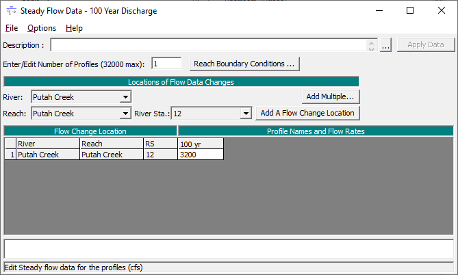
To enter the steady flow profile data, from the main program window Edit and then Steady Flow Data were selected. This activated the Steady Flow Data Editor as shown in the figure below. On the top row of the editor, the number of profiles was chosen to be one. When this number was entered, the table portion of the editor adjusted for this number of profiles. Then, the 100-year flow rate of 3200 cfs was entered at the upstream end of the river reach; there were no flow change locations. Finally, the boundary conditions were entered.
Boundary Conditions
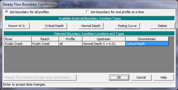
To enter the boundary conditions, the Boundary Conditions icon was selected from the Steady Flow Data Editor (above). This activated the Boundary Conditions Data Editor as shown in the figure below. Since the flow through the river reach is supercritical, the analysis will be performed in the mixed flow regime. This will allow for the computations of both subcritical and supercritical flow profiles, if they are found to occur. Therefore, the user must enter both an upstream and a downstream boundary condition. As can be seen in below, a Normal Depth upstream boundary condition was selected with a slope of 0.01 ft/ft. Additionally, a downstream boundary condition was selected as Critical Depth. The selection of these boundary conditions will be discussed in the analysis of the output. For additional discussion on boundary conditions, the modeler is referred to chapter 7 of the User's Manual. At this point, the flow data was saved as "100 Year Discharge."
Steady Flow Analysis
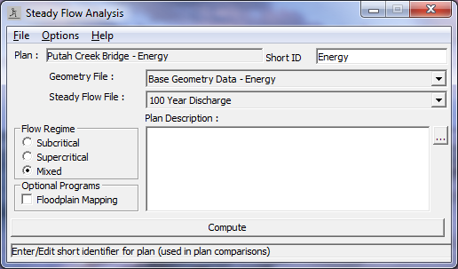
After all of the geometric and steady flow data were entered, the steady flow analysis was performed. This was accomplished by selecting from the main menu Run and then Steady Flow Analysis. This activated the Steady Flow Analysis Window as shown in the figure below.
As shown below, first a Short ID was entered as "Energy." Then the geometry file "Base Geometry Data - Energy" and the steady flow file "100 Year Discharge" were selected by using the down arrows on the right side of the window. (Note: The selection of these files was not necessary since there existed only one geometry file and only one flow file at this time.) Then the Flow Regime was selected as "Mixed" and the information was saved as a plan by selecting File and then Save Plan As. The title "Putah Creek Bridge - Energy" was entered and the OK button was selected. Then this plan title appeared at the top of the steady flow window (as well as on the main program window). Finally, the COMPUTE button was selected to perform the analysis.
Review of Output for Energy Analysis
The modeler can review the output in both graphical and in tabular form. For this analysis, first the water surface profile was plotted and then the profile table and the cross section table for the bridge were reviewed.
Water Surface Profile
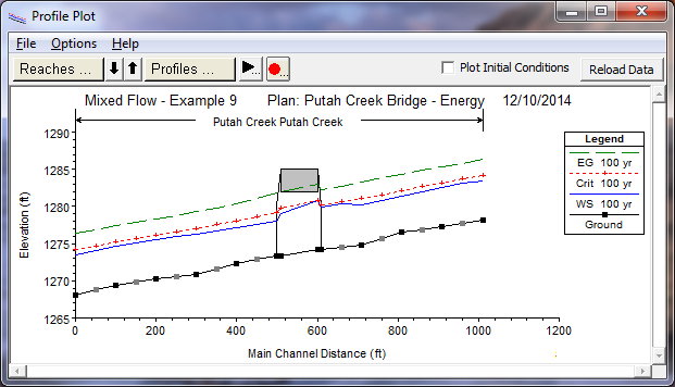
To view the water surface profile, from the main program window select View and then Water Surface Profiles. This will display the profile as shown in the figure below. The profile shows the energy gradeline, the water surface, and the critical depth for the flow of 3200 cfs (the only flow for this example).
To perform the mixed flow analysis, the program will first compute a subcritical flow profile for the entire river reach starting at the downstream river station. The program will flag any location that defaulted to critical depth. Next, the program will perform a supercritical analysis for the river reach starting at the upstream river station. During this phase, the program will compare the specific force for the supercritical flow to the specific force for the subcritical flow at any river station that has a valid answer in both flow regimes. The flow regime with the greater specific force will control at that river station. For a further discussion on mixed flow analysis, the user is referred to the section "Mixed Flow Regime Calculations" in chapter 4 of the Hydraulic Reference Manual.
For this example, it can be seen in the figure below that the flow is supercritical at the upstream end of the river reach because the water surface is below the critical depth line. This was determined by comparing the specific force of the user defined upstream normal depth boundary condition with the subcritical flow answer. The program had determined that the specific force of the supercritical flow boundary condition was greater than that of the subcritical flow answer and therefore used the upstream boundary condition. The program then continued in the downstream direction with a supercritical flow profile.
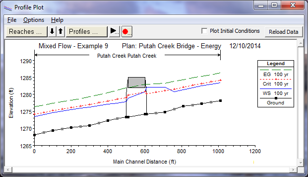
When the program calculated the water surface profile for river station 9, it determined that there was a valid answer for both the subcritical and supercritical flow profiles. The program then compared the specific force of both of these flow regimes and determined that the subcritical flow had a greater specific force. This implies that the flow at river station 9 was subcritical and that a hydraulic jump developed upstream of this river station. This can be seen in figure above to have occurred between the main channel stations of 710 and 760 (river stations 9 and 9.5*). This hydraulic jump occurred because the cross section geometry in the vicinity of the bridge caused a constriction of the flow and a backwater was created upstream from the bridge. This backwater created a subcritical profile immediately upstream of the bridge and a hydraulic jump was necessary for the flow to transition from supercritical to subcritical.
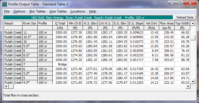
To view the calculated values of the water surface elevations, critical depth, and energy gradeline, the Standard Table 1 profile table was activated from the main program window by selecting View, Profile Summary Tables, and then Std. Table 1. This table is shown in the figure above, and shows a water surface elevation of 1280.84 and a critical water surface elevation of 1281.58 at river station 9.5*. This water surface elevation is less than the critical depth and implies a supercritical flow regime. At river station 9, the water surface elevation of 1282.19 is greater than the critical water surface of 1281.03 and implies a subcritical flow regime. The modeler can use this table to determine all of the computed values that are displayed on the profile plot as shown in the figure preceding the one above.
Referring back to the figure before, as the calculations continued through the bridge, Class B low flow was found to occur since the flow did not encounter the low cord of the bridge and the flow passed through critical depth under the bridge. For Class B low flow, the program will set the water surface at critical depth at either the upstream inside or downstream inside cross section of the bridge. The program will calculate the specific force for critical depth at both of these sections and set the flow at critical depth at the section that is the most constricted and has the greater specific force. For this example, the flow was set at critical depth at the bridge upstream inside cross section, as shown in the second most recent figure. Additionally, if the specific force of both cross-sections are approximately equal, then the program will use the location entered by the user. The location can be selected from within the Bridge/Culvert Data Editor by selecting Options and then Momentum Class B defaults.
Finally, a supercritical profile continued downstream of the bridge to the last downstream cross section. The downstream boundary condition had been set at critical depth. However, the program determined that the supercritical flow solution at the downstream end had a greater specific force than the boundary condition and used the supercritical flow answer.
Water Surface Profiles for Subcritical and Supercritical Flow Analyses
To perform the analysis, the mixed flow regime had been selected. If the user had selected a subcritical or supercritical flow regime for the analysis, the output would have reflected various warnings and notes intended to alert the user of possible inconsistencies with the results. For example, if the user had selected a subcritical flow regime, the water surface profile would have appeared as shown in the figure below.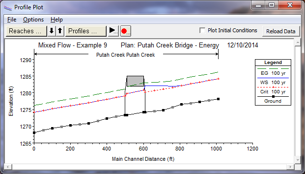
As can be seen in the figure above, the water surface coincided with the critical depth line for the majority of the river stations. A review of the Summary of Errors, Warnings and Notes would reveal the repetition of the warning: "During the standard step iterations, when the assumed water surface was set equal to critical depth, the calculated water surface came back below critical depth. This indicates that there is not a valid subcritical answer. The program defaulted to critical depth." This warning is issued when the user has requested a subcritical flow analysis but the program could not determine a subcritical flow depth at the specified cross section. Since a subcritical solution was not possible, the program used critical depth at this location and continued on with the calculations. This warning may be associated with too long of reach lengths between cross sections or the fact that the flow analysis should be performed in the supercritical or mixed flow regimes.
If the user had selected to perform a supercritical flow analysis, the water surface profile would have appeared as shown in the figure below. As can be seen in the figure, there is an inconsistent drop in the energy gradeline immediately upstream of the bridge. A review of the warnings at the upstream inside bridge cross section revealed that the energy equation could not be balanced within the specified number of iterations and the program defaulted to critical depth at this location. The user should perform the computations in the mixed flow regime to determine if a subcritical flow profile exists in the river reach. The program can only provide for both subcritical and supercritical flow answers when the mixed flow regime is selected.
The analysis of the river reach in the subcritical and supercritical flow regimes are not provided as plans for this example. They were computed and presented to show what would develop if these flow regimes had been selected. However, the modeler can readily select these other flow regimes and execute the program to observe the output. For an additional discussion for the descriptions of the warnings, errors, and notes, the user is referred to example 1 and to chapter 10 of the User's Manual.
Profile Table - Bridge Comparison
Returning to the mixed flow analysis of the river reach, it was observed that during the flow event, Class B low flow was found to occur at the bridge. For the low flow analysis, the energy and the momentum methods had been selected to be computed for the analysis in the Bridge Modeling Approach Editor. To determine which method the program used for the final answer, from the main program window select View, Profile Summary Table, Std. Tables, and then Bridge Comparison. This will activate the Bridge Comparison Profile Table as shown in the figure below.

The first two columns in the table show the reach and river station for the bridge location. For this example, the bridge is located at river station 7. The third column shows the energy gradeline elevation that was used as the final answer for the analysis, 1283.00 ft. The fourth column displays the water surface elevation (1282.21 ft) that corresponds to the energy gradeline in column three. The fifth column displays the bridge method that was selected as the final answer. Finally, the sixth and seventh columns show the results of the energy and momentum methods since these two methods were selected to be computed. As can be seen in the table, the energy low flow method produced a result of 1283.07 ft for the energy gradeline. The momentum method produced a result of 1283.00 for the upstream energy gradeline, and was selected as the final bridge solution. The reason the momentum method was selected, instead of the highest upstream energy answer, is that the bridge is in a class B flow regime (passing from subcritical, through critical, and going supercritical) inside of the bridge. For this type of flow regime, HEC-RAS uses the Momentum equation as the best answer, due to the rapidly varying flow (i.e. the energy method does not perform as well in rapidly varying flow regimes – where flow passes through critical depth, and may go through a hydraulic jump). The only time the momentum method is not used for Class B low flow is if it fails to converge on an answer, then the energy method will be used..
Cross Section Table - Bridge
As an additional review of the output for the bridge, the cross section table was activated from the main program window by selecting View, Cross Section Table, Type, and then Bridge. This displayed the Bridge Cross Section Table as shown in the figure below. For this example, there was only one bridge located on Putah Creek at river station 7. The left side of the table shows the energy and water surface elevations for the river station immediately upstream of the bridge (as shown in the previous figure). The right side of the table displays information for the two cross sections located inside of the bridge. The bottom portion of the table displays any errors, warnings, and notes for the cross section. As is shown in the figure below, two of the notes that appear at this river station notify the modeler that Class B low flow was computed for this bridge structure. Whenever Class B low flow is found to occur, the modeler should perform the analysis in the mixed flow regime mode.
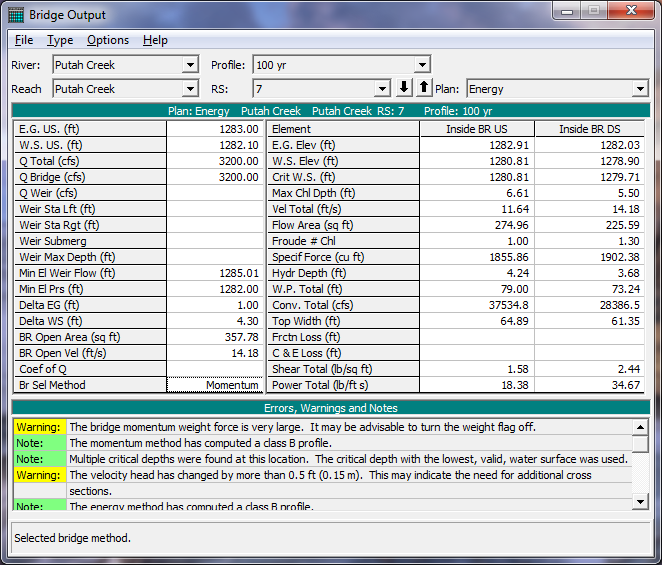
This completed the review for the energy method analysis. As a final review of the water surface profile as shown in the first figure on this page, it can be seen that the water surface upstream of the bridge did not encounter the bridge decking for the energy method analysis and therefore was calculated as a low flow profile. However, the water surface elevation is very close to the bridge decking and, due to the turbulent wave action of the flow, may jump to pressure flow during the event. Therefore, an additional analysis was performed with the pressure/weir flow option selected for the high method. This is discussed further in the next section.
Pressure/Weir Analysis
The water surface profile in the vicinity of the bridge was calculated as low flow for the energy method analysis. However, for a pressure flow analysis, the program will compare the energy gradeline value of the flow with the low cord of the bridge decking to determine when pressure flow will begin to occur. As can be seen in the first figure in Review of Outout for Energy Analysis, the energy gradeline elevation is greater than the low cord at the upstream side of the bridge. Therefore, the river reach was re-analyzed using the pressure/weir method for the high flow computations.
To select the pressure/weir method, the geometry file "Base Geometry Data - Energy" was activated. Then the Bridge/Culvert icon and the Bridge Modeling Approach icon were selected. The "Pressure/Weir Method" was then chosen for the high flow analysis. This Bridge Modeling Approach Editor is shown as in the figure below.
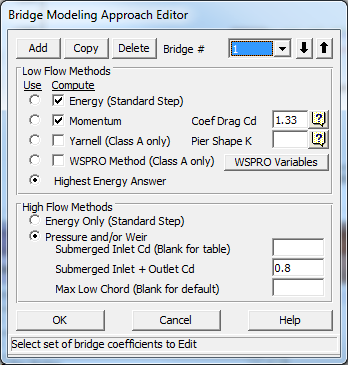
For the pressure/weir analysis, the editor allows three input coefficients. The first coefficient is for the flow situation when only the upstream side of the bridge decking is submerged. For this example, the field was left blank so that the table values would be used by the program. The second coefficient is for the flow situation when both the upstream and downstream sides of the bridge decking are submerged. This coefficient was left at a value of 0.8, the default value. The final field is for the modeler to enter an elevation value for the program to use to determine when to begin the pressure flow calculations. Pressure flow calculations will begin when the low flow energy gradeline value is greater than the value entered in this field. If the field is left blank (as for this example), then the program will use the highest low cord of the bridge decking on the upstream side. Once all of the data had been entered, the editor was closed by selecting the OK button.
Next, the ineffective flow areas were added at river station 8 (the river station located immediately upstream of the bridge). A left ineffective flow area was set to begin 10 feet to the left of the bridge opening and a right ineffective flow area was set to begin 10 feet to the right of the right side of the bridge opening. Both of these ineffective flow areas were set at an elevation of 1285 feet, the high cord elevation of the bridge.
Then, the geometry file was saved as "Base Geometry Data - Press/Weir." Next, this geometry file and the steady flow data file were saved as a plan. This was performed by first activating the Steady Flow Analysis Window from the main program window. The steady flow window is shown in the figure below. Then, the geometry and steady flow file were selected by depressing the down arrows on the right side of the window.
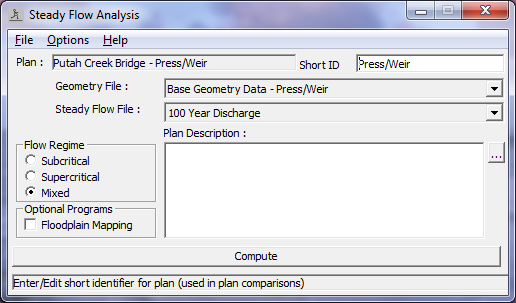
Next, the Short ID "Press/Weir" was entered in the upper right corner of the editor and the flow regime "Mixed" was selected. Finally, File and Save Plan As were selected and the title "Putah Creek Bridge - Press/Weir" was entered. This created a new plan with the pressure/weir geometry file and the steady flow data file. The plan name then appeared at the top of the steady flow analysis window (as well as on the main program window).
After the new plan was created, the COMPUTE button was depressed to activate the calculations of the water surface profile. The user can activate this plan by selecting File, Open Plan, and then the plan "Putah Creek Bridge - Press/Weir" to review the remaining discussion of this example.
Review of Output for Pressure/Weir Analysis
For the output for the pressure/weir analysis, this discussion will review the water surface profile, the expansion and contraction reach lengths, the bridge comparison table, the bridge cross section table, and finally the 3-D plot.
Water Surface Profile
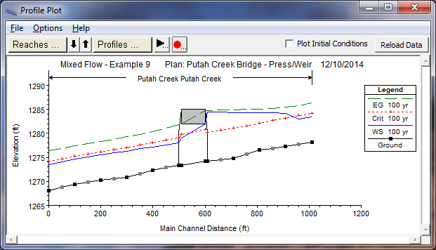
The water surface profile for the pressure/weir analysis is shown in the figure below. As can be seen in the figure, the upstream water surface profile begins in the supercritical flow regime. However, the energy gradeline at the cross section immediately upstream of the bridge was greater than the highest value of upstream low cord. Therefore, during the computations, pressure flow was found to occur and the water surface profile developed as pressure flow through the bridge. This pressure flow caused a backwater effect and created a subcritical flow profile upstream of the bridge. For the flow to transition from a supercritical to a subcritical profile, a hydraulic jump occurred in between river stations 11 and 11.5*.
The flow through the bridge structure is again Class B flow because the flow passed through critical depth within the bridge. Finally, the downstream profile is supercritical to the downstream cross section. As before, it was necessary to perform the analysis in the mixed flow regime in order to obtain a water surface profile in both the subcritical and supercritical flow regimes.
Expansion and Contraction Reach Lengths
As stated previously, the locations of the cross sections in the vicinity of a bridge are crucial for the accurate prediction of the energy losses through the structure. For this example, the distance from river station 6 to 5.5 * defines the expansion reach length and the distance from river station 8.5* to 8 defines the contraction reach length. Each of these reach lengths are evaluated below based upon the procedures as outlined in appendix B of the Hydraulic Reference Manual. However, these procedures were developed based on subcritical flow through bridges. Therefore, only the table values will be used to provide a general guidance for the reach lengths.
Expansion Reach Length. To estimate the expansion reach length from Table B.1, the following information was required:
| b=90 \\B=190 \\ b/B=0.50 \\ S=50 \\ n_{ob} / n_c = 0.035/0.025=1.4 \\ L_{obs} = 45 |
where:
b=bridge opening width, ft
B=floodplain width, ft
S=bed slope, ft/mi
nob =Manning's n value of the overbank
nc=Manning's n value of the main channel
Lobs=average length of obstruction, ft
From Table B.1, the expansion ratio (ER) was determined to be in the range from 1.2 - 1.5. Using an average value of 1.3 yields an expansion reach length (Le) of:
| L_e = (ER)(L_{obs}) = (1.1)(45)=50 \ feet |
From the geometric data, the distance from river station 6 to 5.5* was set at 50 feet. This value is approximately equal to the expansion reach length as determined above and the location of the river stations were not adjusted.
Contraction Reach Length. To estimate the contraction reach length, the contraction ratio from Table B.2 was determined to be in the range from 0.8 - 1.4. Using an average value of 1.1 yielded a contraction reach length (Lc) of:
| L_c = (CR)(L_{obs}) = (1.1)(45) = 50 \ feet |
From the geometric data, the contraction reach length was set to be 50 feet. For this example, the flow in the main channel did not exhibit a large degree of contraction or expansion losses. This allowed for shorter expansion and contraction reach lengths, as determined above. As stated previously, the table values were used as a general guide, because the data of the example were not within the range of the data used to develop the regression equations.
Bridge Comparison Table
As was shown in the figure above, the water surface reflected pressure flow through the bridge structure. To determine why this energy value was selected, the user can review the Bridge Comparison Table. This table is activated from the main program window by selecting View, Profile Summary Table, Std. Tables, and then Bridge Comparison. This table is shown in the figure below.
As described previously, the first two columns in the table show the reach and river station of the bridge location. The third column shows the bridge method that was used as the final answer. The fourth column shows the final energy gradeline value used for the analysis. The fifth column shows the water surface that corresponds to the energy value in column four. The next four columns (Energy, Momentum, Yarnell, and WSPRO) show the calculated energy gradeline values for these low flow methods. For this example, only the energy and the momentum methods were selected to be calculated for the low flow analysis. The solution of the energy gradeline for the energy method is 1282.22 feet. The momentum method produced an answer of 1282.99 feet. Therefore, the program used the value of 1282.99 as the answer for the low flow analysis (this is not necessarily the final answer as is discussed subsequently).

The tenth column (Prs O EG) displays the energy gradeline necessary for only pressure flow to be occurring through the bridge. For this example, this value is 1284.80 feet. The program then compared this pressure only energy gradeline to the energy gradeline that was used for the low flow analysis (1283.07). The greater of the two values was then used as the final answer. For this example, the pressure only energy gradeline was the greater value and the program then used the pressure only method as the final solution.
The ninth column (Prs/Wr EG) shows the calculated energy gradeline value for the situation when both pressure and weir flow would occur. This situation did not develop for this example. For a further discussion for bridge analyses, the user is referred to example 2 and to chapter 6 of the User's Manual and chapter 5 of the Hydraulic Reference Manual.
Bridge Detailed Output Table
As a final table for the review of the pressure/weir flow, the user can select the Bridge Detailed Output Table. This is activated from the main program window by selecting View, Detailed Output Table, Type, and then Bridge. This will display the table as shown in the figure below.
As discussed previously, the left side of the table shows the energy gradeline and the water surface for the cross section immediately upstream of the bridge. (These values are the same as was shown in the figure above) Additionally, the left side of the table shows that there was no weir flow occurring over the bridge decking. The right side of the table displays information for the two cross sections located inside of the bridge.
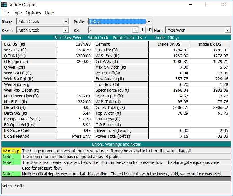
The bottom of the table displays the errors, warnings, and notes for the river station. At this bridge location, the notes shown in the figure indicated that the sluice gate equation was used for pressure flow. This equation was used because the water surface elevation at the river station immediately below the bridge was less than the lowest value of the low cord for the bridge.
X-Y-Z Perspective Plot
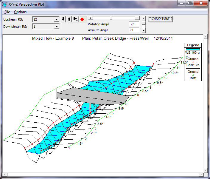
As a final review of the pressure/weir flow analysis, the X-Y-Z Perspective plot was viewed. This plot was activated from the main program window by selecting View and then X-Y-Z Perspective Plots. This plot is shown in the figure below. The user must be aware of the fact that this plot can be aligned according to left or right edges of the cross sections or by the main channel left, centerline, or right bank stations. Additionally, the alignment is based upon the X-coordinates as entered by the user. If the X-coordinates for the cross sections are not all established from the same left baseline, then the plot may not be accurately portraying the correct configuration of the river system.
Summary
As a summary for this example, a profile plot for both the energy and pressure flow analysis is shown in the figure below. Once the plot was activated, Options and Plans were chosen and both plans were selected to be displayed. The heading at the top of the figure displays the Short ID's that were used for each plan : 1) Energy and 2) Press/Weir. The legend displays two lines for the critical depth and two lines for the water surface. Both of the critical depth lines will coincide since the flow rate was the same for both plans. For the water surface profiles, the lines are labeled "WS 100yr - Energy" and "WS 100yr - Pressure" for the energy and pressure methods respectively.
(Note: For this example, each plan only had one profile.) Similarly, the legend description for the solid water surface profile signifies that this line is for the first profile of the energy plan.
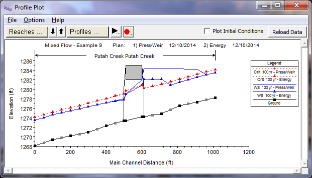
A review of this figure shows a significant difference in the calculated water surface profiles for the two plans. During the energy analysis, the water surface does not encounter the bridge decking and this lead to a low flow profile. However, the pressure analysis determined that the water surface came in contact with the upstream side of the bridge. With both of these analyses, the modeler must use engineering judgment to determine which profile is actually occurring.
Realistically, for this example, as the flow rate begins to increase to the value of 3200 cfs, the flow will most likely be a low flow profile as calculated by the energy method. At the flow rate of 3200 cfs, the flow may also initially be occurring as the low flow profile. However, the water surface immediately upstream of the bridge has risen due to the constriction of the cross sections in the vicinity of the bridge. If the flow is sediment laden and as debris begins to accumulate in the vicinity of the bridge opening, the water surface may begin to fluctuate due to the turbulent nature of the flow. These water surface fluctuations may become great enough to cause the water surface to come in contact with the upstream low cord of the bridge. When this occurs, the flow may "jump" to become pressure flow through the bridge opening.