Download PDF
Download page Method of Slices.
Method of Slices
The Method of Slices methodology included in HEC-RAS follows the more classical geotechnical approach to planar failure. The formulation of the method of slices for bank failure analysis comes from Langendoen (2008). Before the analysis the algorithm divides each user specified material layer into three vertical slices of equivalent width (below). This ensures that the force and momentum balance computed for each segment of the failure plan will not include more than one material type.
 The initial formulation of the method of slices (Bishop, 1955) considered forces acting at the base of each slice (along the failure plane) and included force (below) and momentum balances that were both vertical and normal to the slip surface. The Morgenstern and Price method (1965) added inter-slice forces in their analysis of earthen dams. The algorithms in USDA-ARS BSTEM for HEC-RAS include both inter-slice forces. The forces that act on each slice include: the weight of the slice Wj, the normal force acting on the base of the slice Nj, the shear force induced at the base of the slice Sj, inter slice normal forces Ej, and the vertical shear forces between slices Xj.
Ej and Xj= The inter-slice normal (Ej) and shear (Xj) forces are unique to the method of slices and deserve attention before the algorithm is described. Calculating inter-slice normal forces (Ej) from a horizontal force balance on the slice is relatively straight forward (Equation 4, Inter-slice Shear Forces). However, there is not an elegant theoretical approach to computing inter-slice shear forces. Stress-strain soil data demonstrate that there is a reasonably reliable empirical relationship of the ratio of inter-slice normal (Ej) and shear (Xj) such that:
| X_j = \lambda E_j f(x) = 0.4E_j sin \left( \pi x / L_x \right) |
(4)
where:
λ =the maximum ratio (forty percent),
f(x)=a non-linear function between zero (0) and one (1) that apportions the ratio spatially,
x=the lateral distance into the bank
L=lateral width of the failure plane
In other words, at its maximum (in the center of the failure block) the shear force is forty percent of the normal force (below), and the shear-to-normal ratio decreases for slices farther from the center and closer to the margins.
stress is reduced by f(x) depending on the proximity of the slice to the center of the failure block.")
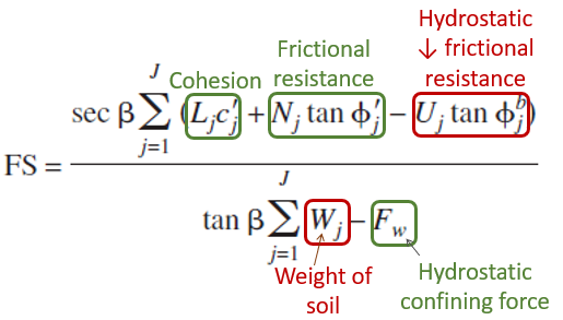
FS can be computed by summing (for all slices, j) the forces acting along the failure plane. The equation for computing FS along the failure slope is a familiar mix (from the Layer Method) of driving (red labels) and resisting (green labels), soil (brown circles) and hydraulic (blue circles) forces in the following equation (Force Balance).
 force
force
where:
FS = factor of safety
U = hydrostatic uplift
P = hydrostatic confining force of the water in the channel
Φ' = friction angle
Φb= relationship between matrix suction and apparent cohesion
c'= effective cohesion
W= weight of the soil
Fw= hydrostatic confining force
This is the Bishop (1955) approach that accounts only for the forces native to the individual slice. However, the normal force at the base of the slice is not a function of the forces intrinsic to the slice itself. It is modified by the inter-slice normal forces on either side (Ej and Ej-1) and the inter-slice shear (Xj and Xj-1) on either side of the slice. An iterative solution including two additional equations is required to compute these effects.
The inter-slice forces are calculated from the horizontal force balance (Equation 6, Horizontal Force Balance) for the slice:
| E_j - E_{j-1} = \left[ W_j - \left( X_j - X_{j-1} \right) \right] tan{\beta} \ \left( c_jL_j + N_j tan{\phi_j^' - U_j tan{\phi^b_j} \right) \frac{sec{\beta}}{FS} |
(6)
Equation 6 has FS imbedded and uses the FS computed in Equation 5. With FS being computed in Equation 5, and the shear forces between neighboring slices (Xj and Xj-1) coming from Equation 6, a Normal force at the base of the slice that is modified for inter-slice effects, can be computed from the vertical force balance (Equation 7) of the slice:
| N_j = \frac {W_j + X_{j-1} - X_j - \left( L_jc_j^' - U_j tan{\phi^b_j} \right) \frac{sin\Beta}{FS}} {cos\beta + \frac{tan{\phi^'_j} sin\beta}{FS}} |
(7)
The new normal force at the base of the slice is then substituted back into Equation 5 to compute a new FS, which is used to update the inter-slice forces in Equation 6 and to update the Normal force in Equation 7. The Method of Slices iterates on these three equations (below) until the change in FS between iterations drops below 0.5 percent.
There are some considerations in the code to decrease the computational expense of iteration. The code checks the denominators of the equations for FS and Nj to determine if iteration is necessary.
