Unlike channel deposition or erosion, toe scour does not affect all nodes equally. This is important for its interaction with the bank failure model because the failure plane will likely pass through the vertical location of maximum scour. However, to compute differential lateral scour, the software must compute a local shear stress for each node.
There are several ways to post process one-dimensional hydraulics to compute local shear stress. The most common is to subdivide the cross section into vertical "prisms" (blue lines in the figure below) and compute a local shear stress based on the hydraulic radius of each one. However, the assumption of zero inter-prism friction only holds along the planes normal to the isovels (contours of constant velocity). Vertical divisions violate this assumption because they are not perpendicular to the isovels.
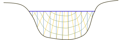
 versus zones (yellow) perpendicular to the isovels (green).")
Alternately, the one-dimensional cross section can be divided into "radial prisms", non-vertical zones by partitions perpendicular to the isovels (yellow lines in the figure above). These approaches will compute different hydraulic radii (a sensitive variable for computing the shear stress) especially in the zone closest to the bank where the toe scour computations are applied. The radial prisms tend to have higher hydraulic radii, and therefore, higher shear stress that the vertical prism associated with the same bank segment and represent a more realistic shear stress distribution (above). Therefore, the bank erosion algorithms use a radial distribution, dividing the flow field, hydraulic radius, and shear stress with radial prisms.
If bed and bank roughness are approximately the same, then we can assume that the line that bisects the toe is normal to the isovels (Kean and Smith, 2001). Therefore, the first step in developing the radial shear distribution is finding the angle bisecting the toe (graph a below). Bank and channel segments are computed by connecting the scour toe (the movable bed limit) to the edge of bank and the next interior channel point respectively (below). This segment determines the zone of the one-dimensional cross section dedicated to toe scour.
Modeling Note:
This computation makes the scour computations sensitive not only to the selection of the mobile bed limits but also to the elevation of the interior node. Random bed fluctuations can cause this node to diverge from the basic lateral channel slope (Figure 20b) which could result in an artificially truncated or enlarged.

Next a "radial prism" is associated with each node (cross section station-elevation points in the toe scour zone). The water surface intersection point connects the midpoint between wetted bank nodes. The water surface intersection point is a relative proportion of the water depth of the midpoint between nodes and the total depth to the midpoint of the movable bed limit and the next interior node (below).

Once the radial flow prism is computed for each wetted bank node (below), the hydraulic radius of the prism is computed from the area and wetted perimeter (water-water boundaries are ignored). Then the shear stress for each radial prism is computed from the average one-dimensional shear stress as a ratio of:
|
\tau_i = \tau_{avg}(R_i/R_{max}) |
where Rmax which is typically Rtoe is the largest hydraulic radius among the radial flow prism.
