Download PDF
Download page 2D Flow Areas.
2D Flow Areas
![]()
Two Dimensional Flow Areas (2D Flow Areas) are regions of a model in which the flow through that region will be computed with the HEC-RAS two dimensional flow computation algorithms. 2D Flow Areas are defined by laying out a polygon that represents the outer boundary of the 2D Flow Area. Then the user must define the computational mesh.
2D Flow Area can be located at the beginning of a reach (as an upstream boundary to a reach), at the end of a reach (as a downstream boundary to a reach), or they can be located laterally to a reach. 2D Flow Areas can be connected to a river reach by using a lateral structure connection. 2D Flow Areas can be connected to another 2D Flow area or a Storage Area by using a SA/2D Area Connection (this is described later in this chapter).
The HEC-RAS 2D modeling capability uses a Finite-Volume solution scheme. This algorithm was developed to allow for the use of a structured or unstructured computational mesh. This means that the computational mesh can be a mixture of 3-sided, 4-sided, 5-sided, etc… computational cells (up to 8 sided cells). However, the user will most likely select a nominal grid resolution to use (e.g. 200 X 200 ft cells), and the automated tools within HEC-RAS will build the computational mesh.
Note: for a more detailed description of how to use the HEC-RAS two-dimensional modeling capabilities, please see the separate User's manual that comes with HEC-RAS called "2D Modeling User's Manual".
A 2D Flow Area, and computational mesh, is developed in the HEC-RAS Geometry editor by doing the following:
Draw a Polygon Boundary for the 2D Flow Area
The user must add a 2D flow area polygon to represent the boundary of the 2D area using the 2D flow area drawing tool in the Geometric Data editor (just as the user would create a Storage Area). The best way to do this in HEC-RAS is to first bring in terrain data and aerial imagery into HEC-RAS Mapper. Once you have terrain data and various Map Layers in RAS Mapper, they can be displayed as background images in the HEC-RAS Geometry editor. Additionally, the user may want to bring in a shapefile that represents the protected area, if they are working with a leveed system. The background images will assist the user in figuring out where to draw the 2D flow area boundaries in order to capture the tops of levees, floodwalls, and any high ground that will act as a barrier to flow.
Use the background mapping button on the HEC-RAS Geometry editor to turn on the terrain and other Map Layers, in order to visualize where the boundary of the 2D Flow Area should be drawn.
For levees and roadways this is obviously the centerline of the levee and the roadway. However, when using a lateral structure to connect a main river to the floodplain (when there is no actual levee), try to find the high ground that separates the main river from the floodplain. Use this high ground as a guide for drawing the 2D boundary, as well as defining the Lateral Structure Station Elevation data.
To create the 2D Flow Area, use the 2D Flow Area tool (the button on the Geometric Editor Tools Bar labeled 2D Flow Area, highlighted in red on Figure 12). Begin by left-clicking to drop a point along the 2D Flow Area polygon boundary. Then continue to use the left mouse button to drop points in the 2D Flow Area boundary. As you run out of screen real-estate, right-click to re-center the screen. Double-click the left mouse button to finish creating the polygon. Once you have finished drawing the 2D area polygon by double clicking, the interface will ask you for a Name to identify the 2D Flow Area. Shown in Figure 5-41 is an example 2D Flow Area polygon for an area that is protected by a levee. The name given to the 2D Flow Area in this example is: "2D Interior Area".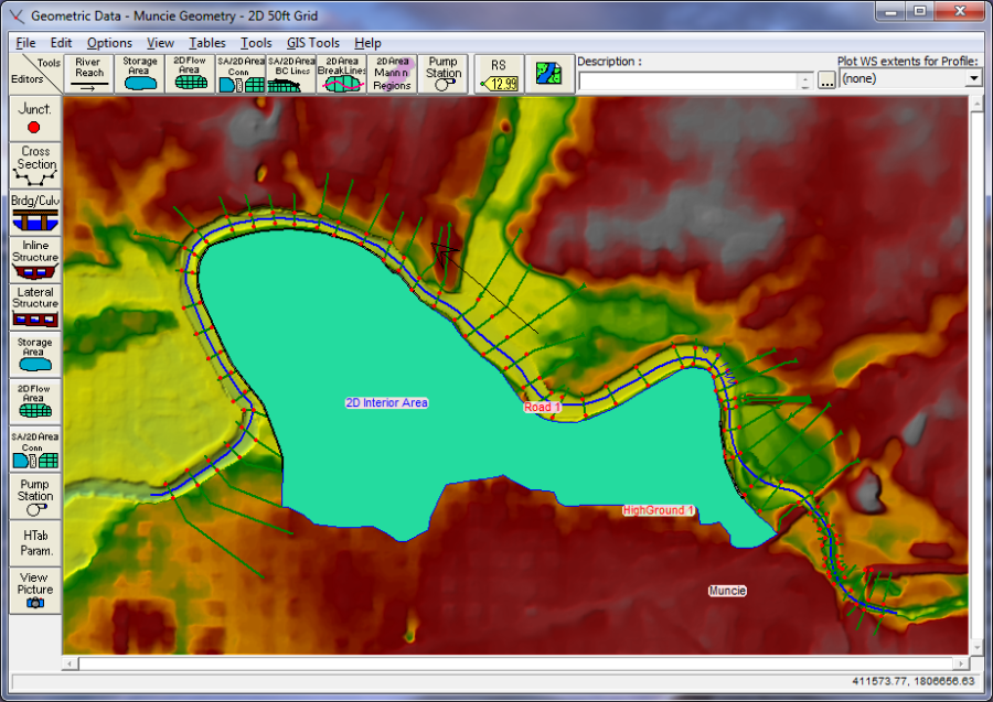
Figure 5 41. Example 2D Flow Area polygon.
Adding Break Lines inside of the 2D Flow Area
Before the computational mesh is created the user may want to add break lines to enforce the mesh generation tools to align the computational cell faces along the break lines. Break lines can also be added after the main computational mesh is formed, and the mesh can be regenerate just around that break line. In general, break lines should be added to any location that is a barrier to flow, or controls flow/direction.
Break lines can be imported from Shapefiles (GIS Tools/Breaklines Import from Shapefile); drawn by hand; or detailed coordinates for an existing breakline can be pasted into the break line coordinates table (GIS Toools/Breaklines Coordinates Table). To add break lines by hand into a 2D flow are, select the 2D Area Break Line tool (highlighted in Red in Figure 3-2), then left click on the geometry window to start a break line and to add additional points. Double click to end a break line. While drawing a breakline, you can right click to re-center the screen in order to have more area for drawing the breakline. Once a break line is drawn the software will ask you to enter a name for the break line. Add break lines along levees, roads, and any high ground that you want to align the mesh faces along. Break lines can also be placed along the main channel banks in order to keep flow in the channel until it gets high enough to overtop any high ground berm along the main channel.