Download PDF
Download page Pump Stations.
Pump Stations
![]()
A pump station can be used to pump water between two storage areas, a storage area and a river reach, between two river reaches, a river reach and a 2D Flow Area, a Storage Area and a 2D Flow Area, between two 2D Flow Areas, or from one cell to another cell within the same 2D Flow Area. Each pump station can have up to ten different pump groups, and each pump group can have up to twenty identical pumps. To add a pump station to the system, select the Pump Station drawing tool at the top of the geometric data editor. When this button is pressed, move the mouse to the location that represents where the pump station will be located, and click the left mouse button. An editor will pop up asking you to enter a name for the Pump Station. This will establish a pump station location and Icon.
Once a pump station is added to the system, the user must edit the pump station and fill in the required data. To bring up the pump station editor, select the pump station editor button on the left hand side of the geometric data editor, or move the mouse over the pump station icon on the schematic, press down on the left mouse button, then select Edit Pump Station. When the Pump Station editor is selected, the following window will appear: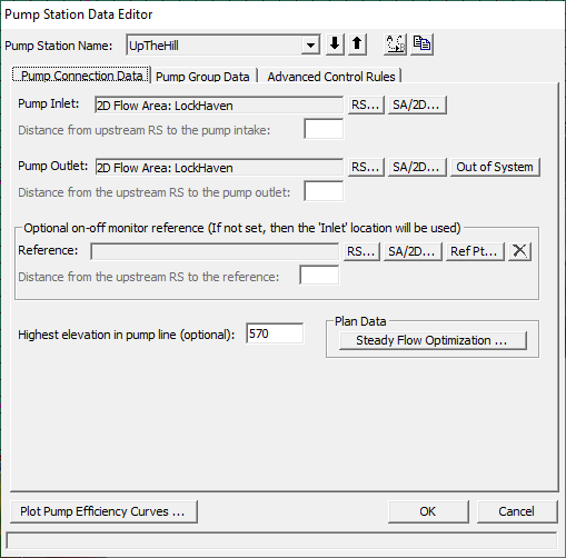
Figure 5 56 Pump Station Editor with Pump Connection Data
As shown in Figure 5 56, there are three tabs on the pump station editor, the first is for the pump connection data, the second is for the pump group data, and the third is for applying advanced rule controls over the pump station. The Pump Connection Data contains the following data:
Rename Pump Station: This option allows the user to rename the pump station to something other than the default.
Pump Inlet: This is the location of where the pump station is pumping from. This can be either a storage area, 2D Flow Area, or a river station from a river reach. The Set RS button allows the user to connect a pump from a river station of a reach, the Set SA/2D button allows the pump to be connected from a Storage Area or a 2D Flow Area.
Pump Outlet: This is the location of where the pump station is pumping to. This can be either a storage area or 2D Flow Area (use Set SA/2D button) or a river station from a river reach (use Set RS button).
Optional On-Off Monitor Reference: By default the program uses the "Pump Inlet" location to determine when the pump should turn on or off. However, the user has the option to set a different location to be used as the monitor point for determining whether the pump should be turned on or off. This optional monitor location can be a storage area, 2D Flow Area (if you are using a 2D Flow Area, you must add a reference point into the geometry data within that 2D flow Area); or a river station within a river reach.
Highest elevation in pump line: This option allows the user to enter an elevation to be used as the highest elevation in the pump line. One example of where this may be useful is if a pump station was being used to pump water over top of a levee. In this situation, the too and from water surface elevations does not completely quantify the required head to pump the water over the levee. So it is necessary to enter the elevation of the highest point in the pump line (top of the levee) in order to accurately compute the flow going through the pump.
Steady Flow Optimization: This option is for steady flow modeling only. If water is being pumped from or to a river reach, the amount of flow going into or out of the reach should be accounted for when computing the water surface profiles. However, the water surface profiles will affect the computation of the amount of flow through the pumps. Therefore, to calculate this accurately, the pump flow and water surface profiles must be calculated iteratively until a balance is found between the river flows and the pump flows. This optimization feature is not done automatically by the steady flow program, however, the user can have the program do this by selecting Steady flow optimization. When this option is selected, a window will appear allowing the user to turn the pump flow optimization on.
In addition to the pump connection data the user must fill out the pump group data. Select the Pump Group Data tab and the editor will look like the following (Figure 5-57):
Figure 5 57 Pump Station Editor with Pump Group Data
As shown in Figure 5-57, the pump group data consists of the following:
Pump Group Name: By default the first pump group is called "Group #1", and the second would be "Pump Group #2", etc. The user has the option to rename any pump group to whatever they would like. This is done by pressing the "Rename Group" button.
Add Group: This button is used to add another pump group. If you have pumps that have different flow capacities and use different pump efficiency curves, they must be entered as a separate pump group.
Rename Group: This allows you to rename a pump group.
Delete Group: This button is used to delete the current pump group.
Bias group operations to on (Steady Flow Only): This option is only relevant for a steady flow run. When this option is selected, and a particular water surface profile is between the on and off elevation for a pump, the program will assume the pump is turned on. If this option is not checked, then the program will assume the pump is off when the water surface is between the on and off elevations.
Startup (min): This option is used for unsteady flow only. When a pump is triggered to turn on, the default operation is that the pump turns on instantly and starts pumping to full capacity the very next time step. This option allows the user to enter a start up time in which the pumps will transition from zero flow to full capacity over the user entered time step in minutes. This option is very useful to prevent the unsteady flow computations from going unstable when to large of a flow change is experienced from a pump turning on.
Shutdown (min): This option is used for unsteady flow only. When a pump is triggered to turn off, the default operation is that the pump turns off instantly and stops pumping the very next time step. This option allows the user to enter a shut down time in which the pumps will transition from full capacity to zero flow over the user entered time step in minutes. This option is very useful to prevent the unsteady flow computations from going unstable when to large of a flow change is experienced from a pump turning off so abruptly.
Pump Width: This field is only used for drawing the width of the pump line onto the geometric data window.
Number of Pumps in Group: This field is used to enter the number of identical pumps in the current pump group. Identical pumps must use the same pump efficiency curve but can have different on and off trigger elevations.
Pump Efficiency Curve: This table is used to enter the pump efficiency curve, which is a table of static heads versus flow rates. The head represents the total head in the system, which is normally the difference in the water surface elevations between the from and the to location. Note: The entered flow is the pump rate capacity at that particular head. In HEC-RAS, the flows entered for a given head difference, must already account for all energy losses in the pump line (friction, bends, junctions, etc…). Do not enter the rated pump curve from the manufacturer, that curve does not account for losses in the pump line. An example of how to compute a pump efficiency curve is shown in Figure 5-58 below. As shown in Figure 5-58, the user must compute all energy losses in the system, between the two static pools. The energy losses in the line are subtracted from the manufacturer pump efficiency curve to get the curve for use in HEC-RAS. The pump efficiency curve can be plotted for visual inspection by pressing the Plot Pump Curves button at the bottom of the window.
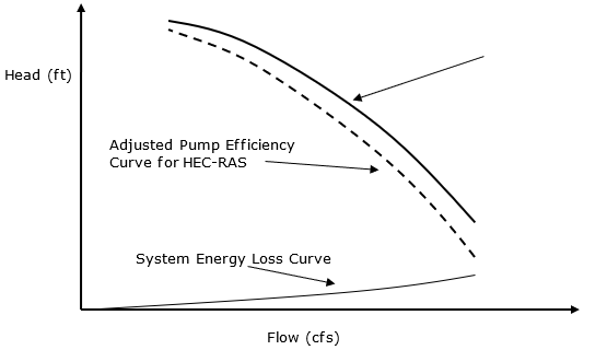
Pump Efficiency Curve for HEC-RAS
Pump Operations: This table is used to define the trigger elevations for when the pumps will turn on and off. The monitor location for triggering a pump on or off is by default the from location, unless otherwise specified in the Optional On-Off Reference field. In general, the pump on elevation must be higher than the pump off elevation. Trigger elevations must be specified for all of the pumps. If the user puts the pump off elevation higher than the pump on elevation, then the pump turns on when the water surface goes below the on elevation, and the pump remains on until the water surface gets higher than the pump off elevation. This would be for example, pumping water up to a storage tank. When the pump off elevation is lower than the pump on elevation (typical way of using it), the pump turns on when it goes above the on elevation, and the pump turns off when it goes below the off elevation. This is the typical use of the pumps for interior ponding areas.
The bottom half of the window shows a table with all the individual pumps in the group. The table contains the following:
Pump Name: This field contains the name of each of the individual pumps. Pumps are automatically names "Pump #1", then "Pump #2", etc. The user can double click in the Pump Name field and change these names to be more specific to the location.
WS Elev On: This is the elevation at which the pump will be turned on. This is based on the elevation of the water surface at the "Inlet" location connected to the pump.
WS Elev Off: This is the elevation at which the pump will be turned off. This is based on the elevation of the water surface at the "Inlet" location connected to the pump.
Pump GIS Data: Another table directly to the right of the individual Pump Name table, is a table containing the GIS coordinates of the individual pumps. If the user clicks on a pump row in the Pump Names table (ex, if Pump #1 was selected), then the X, Y coordinates in the
Pump Coordinates table are for Pump #1. If another Pump is selected, then the X, Y coordinates will be for that pump. Entering X, Y coordinates for a pump is only need when connecting pumps to 2D Flow Areas. This is required in order to figure out which cell(s) the pump is connected to in the 2D Flow Area. User must draw a spatial line that goes from the Pump Inlet to the Pump Outlet. This line will be used to show the Pump connection spatially in the Geometric Data editor, as well as establish which cell the pump is connected to. X, Y coordinates are not required if you are not connecting pumps to a 2D Flow Area. But if even one end of the pump is connected to a 2D Flow Area, the X, Y coordinates are required.
The final tab, labeled Advanced Control Rules, is an optional tab used to specify rules that will override the physical pump data. When this tab is selected the editor will appear as follows: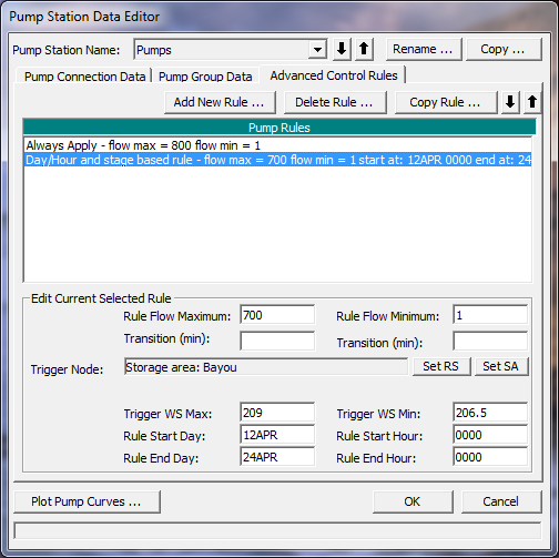
5 59. Pump Editor with Advanced Control Rules Tab Selected.
As shown in the Figure 5-59 the Advanced Control Rules tab has three buttons at the top of the editor, Add New Rule; Delete Rule, and Copy Rule. The Delete Rule button will delete the currently selected rule from the list of pump rules shown in the text box labeled Pump Rules. The Copy Rule button makes a copy of the currently opened rule. The Add New Rule button allows the user to enter a new rule. When this button is selected an editor will appear as shown below:
5 60. Rule Types Editor.
As shown in Figure 5-60, there are six types of rules that can be applied to a pump station. Each of the six rule types allow the user to specify a minimum and maximum flow for the entire pump station. This minimum and maximum flow will narrow the range of possible flows that have been computed for the pump station based on the physical pump data. The rule types only differ in how and when the minimum and maximum flow range gets applied.
The first rule type, Always apply this rule, is applied at for all time steps in the solution. The second rule type, Apply Based on Target Flow, is applied only when a target minimum and/or maximum flow is exceeded (flow is greater than specified maximum or less than specified minimum) at a user specified flow monitoring location. The flow monitoring location can be a cross section within a river reach, or a storage area. The third rule type, Apply based on target WS, is applied only when a target minimum and/or maximum water surface elevation is exceeded (stage is greater than specified maximum or less than specified minimum) at a user specified stage monitoring location. The fourth rule type, Apply based on Day/Hour, is only applied only during a user specified time window. The user enters a starting day and time, and an ending day and time. The specified maximum and minimum flows are then applied to the pump station only during the user specified time window. The fifth rule type, Apply based on day/hour and flow, is a combination of a user specified time window, and a maximum and/or minimum flow target at a user specified flow monitoring location. The last rule type, Apply based on day/hour and WS, is a combination of a user specified time window, and a maximum and/or minimum stage target at a user specified stage monitoring location.
The user can also apply a transition time in minutes to the maximum and minimum flow for each of the rules. Therefore if a rule will change the flow from the currently computed value to a user entered maximum, the transition time is used to allow for the flow change to occur over a user specified time. This same concept is used for the minimum flow rate also.
The user can specify as many rules as they want for each pump station. The rules will be applied to the pump station in the order that they have been entered (which is also the order in which they appear in the editor). The user can move a rule up or down in the list by highlighting a rule, then using the up and down arrow buttons to move the rule.
After all of the pump data are entered, press the OK button to have the data excepted by the program. This does not save the data to the hard disk, it only allows it to be used in the current execution of the program. To save the data permanently, you must save the geometry data from the File menu of the Geometric Data Editor.