Download PDF
Download page Dam Break Analysis.
Dam Break Analysis
The failure of several dams in this country (Buffalo Creek, West Virginia 1972; Teton dam, Idaho 1976; Laural Run Dam and Sandy Run Dam, Pennsylvania 1977; Kelly Barnes Dam, Georgia 1977; and others), has led our nation to take a strong look at dam safety. One aspect of dam safety is to answer the question, "What will happen if the dam were to fail?" The ability to evaluate the results of a dam failure has been added into the HEC-RAS software.
HEC-RAS can be used to model both overtopping as well as piping failure breaches for earthen dams. Additionally, the more instantaneous type of failures of concrete dams can also be modeled. The resulting flood wave is routed downstream using the unsteady flow equations. Inundation mapping of the resulting flood can be done with the RAS-Mapper portion of the software when GIS data (terrain data) are available.
Dams are modeled within HEC-RAS by using the Inline Structure editor or the SA/2D Area Connection (for 2D modeling). Each of these editors allows the user to put in an embankment, define overflow spillways and weirs, gated openings (radial and sluice gates), culverts, rating curves, and time series of flow releases. Gated openings can be controlled with a time series of gate openings or using the elevation control gate operation feature in HEC-RAS. For more information on modeling inline hydraulic structures within HEC-RAS, please review Chapter 5 of this manual (Entering and Editing Geometric Data).
The lake area upstream of the dam can either be modeled with cross sections, a storage area (Figure 14-4.), or a 2D Flow Area. If cross sections are used, then HEC-RAS will perform full unsteady flow routing through the reservoir pool and downstream of the dam. If a storage area is used, HEC-RAS uses level pool routing through the lake, then unsteady flow routing downstream of the dam. If a 2D Flow Area is used then full 2D modeling can be used within the reservoir pool and downstream of the dam. When using a storage area to represent the reservoir pool, HEC-RAS requires two cross sections inside of the reservoir pool, then the inline structure representing the dam, and then the downstream cross sections (see Figure 14-4). The routing reach is hydraulically connected to the reservoir (storage area) with the first (most upstream) cross section. This cross sections water surface is forced to the elevation of the water surface in the storage area during the unsteady flow routing. The second cross section in the pool area is required as a bounding cross section for the inline structure (the dam).
One additional caution for using a storage area to represent the pool area: When the initial conditions are computed by backwater analysis, it is up to the user to ensure that the water surface computed just upstream of the dam (for the two cross sections) is consistent with the starting water surface entered for the storage area. If this is not the case, the model will most likely have stability problems at the very start of the unsteady flow routing. There are two ways to ensure these water surfaces are consistent. The first is to adjust the low flow gate openings and initial base flow in the reach to produce a water surface that is consistent with the desired starting pool elevation. The second way is to use the option that allows the user to force the water surface at a cross section during the initial conditions calculations. This option is called Internal RS Initial Stages, and is available from the Options menu of the Unsteady Flow Data editor. This option can be used to set the water surface just upstream of the dam to the same elevation as the storage area.
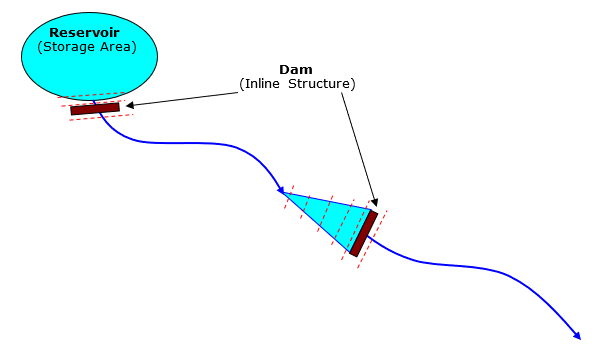
Figure 14 4. Alternate Methods for Modeling a Dam and Reservoir Pool in HEC-RAS.
An example of using the Inline Structure feature to model a dam is shown in Figure 14-5. As shown in the Figure, the user enters the embankment and overflow spillway as one piece using the Weir/Embankment editor. The embankment is shown as the gray filled in area above the ground. The overflow spillway is the rectangular notch on the upper left hand side of the embankment. The main outlet works consist of two rectangular gates, which are entered through the gate editor. The gates are shown towards the bottom of the embankment in this example. 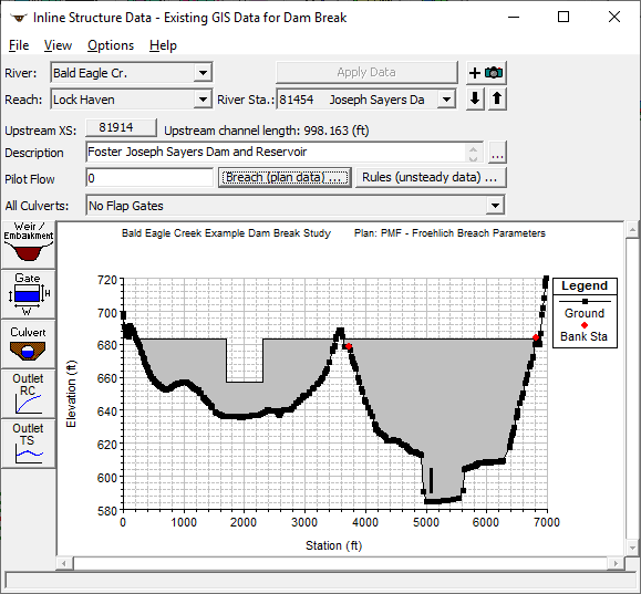
Figure 14 5. Inline Structure Editor with Example Dam Shown