Download PDF
Download page Bridges and Culverts.
Bridges and Culverts
![]()
Once all of the necessary cross-section data have been entered, the modeler can then add any bridges or culverts that are required. HEC-RAS computes energy losses caused by structures such as bridges and culverts in three parts. One part consists of losses that occur in the reach immediately downstream from the structure where an expansion of flow takes place. The second part is the losses at the structure itself, which can be modeled with several different methods. The third part consists of losses that occur in the reach immediately upstream of the structure where the flow is contracting to get through the opening.
The bridge routines in HEC-RAS allow the modeler to analyze a bridge with several different methods without changing the bridge geometry. The bridge routines have the ability to model low flow (Class A, B, and C), low flow and weir flow (with adjustments for submergence), pressure flow (orifice and sluice gate equations), pressure and weir flow, and high flows with the energy equation only. The model allows for multiple bridge and/or culvert openings at a single location.
The culvert hydraulics in HEC-RAS are based on the Federal Highway Administrations (FHWA) standard equations from the publication Hydraulic Design of Highway Culverts (FHWA, 1985), for inlet control situations, and a detailed energy balance into, through, and out of the culvert, for outlet control computations. The culvert routines include the ability to model circular, box, elliptical, arch, pipe arch, low profile arch, high profile arch, semi circular culverts, and ConSpan culvert shapes. The HEC-RAS program has the ability to model multiple culverts at a single location. The culverts can have different shapes, sizes, elevations, and loss coefficients. The user can also specify the number of identical barrels for each culvert type. Culverts can also be buried into the ground and have different roughness coefficients for the bottom, versus the top and sides.
Cross Section Locations
The bridge and culvert routines utilize four user defined cross sections in the computations of energy losses due to the structure. A plan view of the basic cross section layout is shown in the figure below.
Cross section 1 is located sufficiently downstream from the structure so that the flow is not affected by the structure (i.e., the flow has fully expanded). This distance should generally be determined by field investigation during high flows. However, generally field investigation during high flows is not possible. The expansion distance will vary depending upon the degree of constriction, the shape of the constriction, the magnitude of the flow, and the velocity of the flow. If no detailed information is available, a rough estimate of a 2:1 expansion ratio can be used for a first cut estimate of the expansion reach length. Additionally, the table below offers ranges of expansion ratios, which can be used for different degrees of constriction, different slopes, and different ratios of the overbank roughness to main channel roughness. Once an expansion ratio is selected, the distance to the downstream end of the expansion reach (the distance Le) is found by multiplying the expansion ratio by the average obstruction length (the average of the distances A to B and C to D).
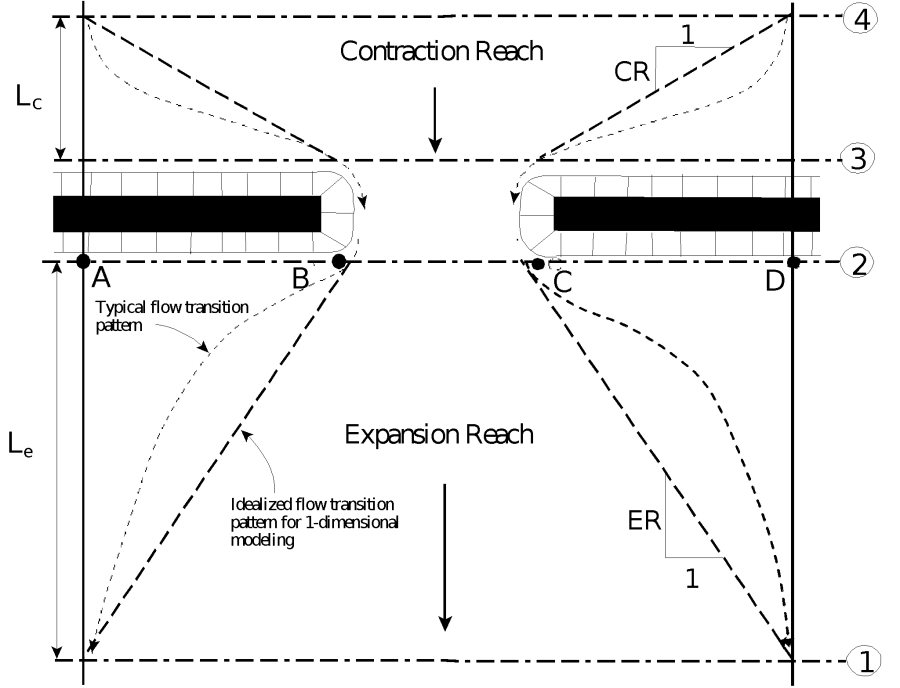
Cross Section Locations at a Bridge or Culvert
The average obstruction length is half of the total reduction in floodplain width caused by the two bridge approach embankments. In table below, b/B is the ratio of the bridge opening width to the total floodplain width, nob is the average Manning n value for the overbanks, nc is the n value for the main channel, and Slope is the average longitudinal bed slope through the bridge reach. The values in the interior of the table are the ranges of the expansion ratio. For each range, the higher value is typically associated with a higher discharge.
Ranges of Expansion Ratios
Opening Ratio | Slope | nob / nc = 1 | nob / nc = 2 | nob / nc = 4 |
|---|---|---|---|---|
| b/B = 0.10 | 1 ft/mile 5 ft/mile 10 ft/mile | 1.4 – 3.6 | 1.3 – 3.0 | 1.2 – 2.1 |
b/B = 0.25 | 1 ft/mile | 1.6 – 3.0 | 1.4 – 2.5 | 1.2 – 2.0 |
b/B = 0.50 | 1 ft/mile | 1.4 – 2.6 | 1.3 – 1.9 | 1.2 – 1.4 |
A detailed study of flow contraction and expansions at bridges was undertaken by the Hydrologic Engineering Center. The results of this study have been published as a research document entitled "Flow Transitions in Bridge Backwater Analysis" (RD-42 HEC, 1995). The purpose of this study was to provide better guidance to hydraulic engineers performing water surface profile computations through bridges. Specifically the study focused on determining the expansion reach length, Le; the contraction reach length, Lc; the expansion energy loss coefficient, Ce; and the contraction energy loss coefficient, Cc. A summary of this research, and the final recommendations, can be found in Appendix B of the HEC-RAS Hydraulic Reference manual.
The user should not allow the distance between cross section 1 and 2 to become so great that friction losses will not be adequately modeled. If the modeler feels that the expansion reach will require a long distance, then intermediate cross sections should be placed within the expansion reach in order to adequately model friction losses. The user will need to estimate ineffective flow areas for these intermediate cross sections.
Cross section 2 is located a short distance downstream from the bridge or culvert. This cross section should represent the natural ground (main channel and floodplain) just downstream of the bridge or culvert. This section is normally located near the toe of the downstream road embankment. This cross section should Not be placed immediately downstream of the face of the bridge deck or the culvert opening (for example some people wrongly place this cross section 1.0 foot downstream of the bridge deck or culvert opening). Even if the bridge has no embankment, this cross section should be placed far enough from the downstream face of the bridge to allow enough distance for some flow expansion due to piers, or pressurized flow coming out of the bridge. If a culvert is being modeled, the culvert routines automatically account for an exit loss. Therefore, cross section 2 should be located far enough downstream from the culvert to capture the immediate expansion of flow in which the exit losses occur over. This distance will vary with the size of the bridge opening or culvert.
Cross section 3 should be located a short distance upstream from the bridge or culvert. This distance should only reflect the length required for the abrupt acceleration and contraction of the flow that occurs in the immediate area of the opening. Cross section 3 represents the natural ground of the channel and overbank area just upstream of the road embankment. This section is normally located near the toe of the upstream road embankment. This cross section should Not be placed immediately upstream of the bridge deck or culvert opening (for example some people wrongly place this cross section 1.0 foot upstream of the bridge deck or culvert opening). The bridge and culvert routines used between cross sections 2 and 3 account for the contraction losses that occur just upstream of the structure (entrance losses for the culvert routines). Therefore, this cross section should be place just upstream of the area where the abrupt contraction of flow occurs to get into the bridge opening or culvert. This distance will vary with the size of the bridge opening or culvert.
Both cross sections 2 and 3 will have ineffective flow areas to either side of the bridge or culvert opening during low flow and pressure flow. In order to model only the effective flow areas at these two sections, the modeler should use the ineffective flow area option. This option is selected from the cross section data editor. For a detailed discussion of how to set the ineffective flow area stations and elevations, see Chapter 5 of the Hydraulic Reference manual.
Cross section 4 is an upstream cross section where the flow lines are approximately parallel and the cross section is fully effective. In general, flow contractions occur over a shorter distance than flow expansions. The distance between cross section 3 and 4 (the contraction reach length, Lc) should generally be determined by field investigation during high flows. Traditionally, the Corps of Engineers recommends locating the upstream cross section a distance equal to one times the average length of the side constriction caused by the structure abutments (i.e. 1:1 contraction ratio). The 1:1 contraction ratio is a reasonable first estimate for placing cross section 4 if no other detailed information or field data is available to further refine that estimate. The contraction distance will vary depending upon the degree of constriction, the shape of the constriction, the magnitude of the flow, and the velocity of the flow. As mentioned previously, the detailed study "Flow Transitions in Bridge Backwater Analysis" (RD-42, HEC, 1995) was performed to provide better guidance to hydraulic engineers performing water surface profile computations through bridges. A summary of this research, and the final recommendations, can be found in Appendix B of the HEC-RAS Hydraulic Reference manual.
When the user adds a bridge at a particular river station, the program automatically formulates two additional cross sections inside of the bridge structure. The geometry inside of the bridge is a combination of the bounding cross sections (2 and 3) and the bridge geometry. The bridge geometry consists of the bridge deck, abutments if necessary, and any piers that may exist. The user can specify different bridge geometry for the upstream and downstream sides of the structure if necessary. Cross section 2 and the structure information on the downstream side are used as the geometry just inside the structure at the downstream end. Cross section 3 and the upstream structure information are used as the bridge geometry just inside the structure at the upstream end. The user has the option to edit these internal bridge cross sections, in order to make adjustments to the geometry.
For a more detailed discussion on laying out cross sections around bridges and culverts, the user is referred to chapters 5 and 6 of the Hydraulic Reference Manual.
Contraction and Expansion Losses
Losses due to the contraction and expansion of flow between cross sections are determined during the standard step profile calculations. Contraction and Expansion losses are described in terms of coefficient times the absolute value of the change in velocity head between adjacent cross sections. When the velocity head increases in the downstream direction a contraction coefficient is used; and when the velocity head decreases in the downstream direction, an expansion coefficient is used. For a detailed discussion on selecting contraction and expansion coefficients at bridges, the user is referred to chapter 5 of the HEC-RAS Hydraulic Reference Manual.