Download PDF
Download page Stream Junctions.
Stream Junctions
Entering Junction Data
![]()
Stream junctions are defined as locations where two or more streams come together or split apart. Junction data consist of a description; reach lengths across the junction; tributary angles; and modeling approach. To enter junction data the user presses the Junction button on the Geometric Data window (Figure 5-1). Once the junction button is pressed, the junction editor will appear as shown in Figure 5-10. 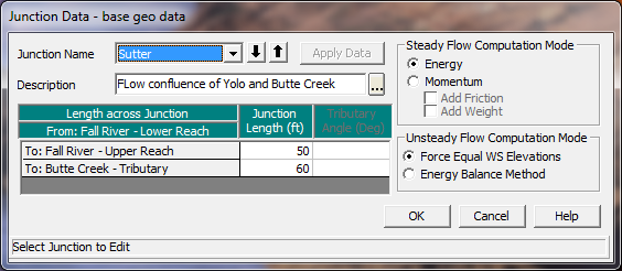
Figure 5 10 Junction Data Editor
The junction editor will come up with one of the junctions loaded. Fill out the description and reach lengths for the junction. Reach lengths across the junction are entered here instead of the cross section data editor. This allows for the lengths across very complicated confluences (i.e., flow splits) to be accommodated. In the cross section data, the reach lengths for the downstream cross section of each reach upstream of the junction will be overridden by the lengths in the junction editor.
When laying out cross sections around a junction (Upstream and downstream on the main stem river and tributaries connected to the junction), place the cross sections as close to the junction as possible. This is especially important for unsteady flow modeling, as the default computational option is that the model assumes the same water surface elevation at all cross sections bounding the junction. If this is a bad assumption, turn on the option labeled "Energy Balance Method" under the Unsteady Flow Computational Method. Cross sections laid out very far from the junction can lead to model stability issues if the elevation of the channel bottom for the cross sections that bound the junction are very different (Have very different invert elevations).
Selection a Modeling Approach
For steady flow hydraulics in HEC-RAS, a junction can be modeled by either the energy equation or the momentum equation. The energy equation does not take into account the angle of a tributary coming in or leaving, while the momentum equation does. In most cases the amount of energy loss due to the angle of the tributary flow is not significant, and using the energy equation to model the junction is more than adequate. However, there are situations where the angle of the tributary can cause significant energy losses. In these situations it would be more appropriate to use the momentum approach. When the momentum approach is selected, an additional column is added to the table next to the junction lengths. This column is used to enter an angle for any river reach that is coming into or exiting the main river. For the reaches that are considered to be the main river, the angle should be left blank or set to zero. Also, the user has the option to turn friction and weight forces on or off during the momentum calculations. The default is to have the weight force turned off.
For unsteady flow hydraulics there are two options for modeling the hydraulics at a junction. The default option makes some simplifying assumptions for the hydraulics at a junction. If the junction is a normal flow combining junction, then all cross sections that bound the junction are given the same water surface each time step, based on the computed water surface at the downstream side of the junction. If the junction is a flow split the water surfaces at the junction are based on the computed water surface at the upstream side of the junction. This simplifying assumption requires user's to place cross sections fairly close together around a junction, depending on the slope of the stream. If cross sections are too far apart, model stability problems can arise from the force water surfaces at all cross sections that bound the junction.
A new junction hydraulics option called the Energy Balance Method has been added for unsteady flow modeling. When this option is turned on, an energy balance is performed across the junction in order to compute the water surfaces, rather than forcing them to all be the same. This is a very useful option for medium to steep streams, or where junction reach lengths are fairly lengthy.
If there is more than one junction in the river schematic, the other junctions can be selected from the Junction Name box at the upper left corner of the window. Enter all the data for each junction in the river system then close the window by pressing the OK button in the lower left corner of the window. When the junction data editor is closed the data are automatically applied.