Download PDF
Download page Uniform Flow Computations.
Uniform Flow Computations
The uniform flow computations are performed by opening the Hydraulic Design Functions window and selecting the Uniform Flow from the Type menu item. Once this option is selected the program will automatically go to the geometry file and plot a cross section with the station and elevation data entered into the table. The user can select any cross section from the available rivers and reaches. The Hydraulic Design window for uniform flow will appear as shown in Figure 13-1.
As shown in Figure 13-1, the Uniform Flow window contains the input data, a graphic, and a window for summary results. Input data tabs included are the S/Q/y/n tab and the Width tab. The S/Q/y/n tab is used for calculating the normal slope, discharge, depth, or roughness for the current cross section. The Width tab is used to calculate the bottom width for a uniform flow solution of a user-entered compound channel (with up to 3 trapezoidal templates). The station, elevation, and roughness values for both the current cross section and the user-defined cross section can easily be manipulated in the table and applied to the current geometry file. The user is required to enter only a minimal amount of input and the computations can be performed.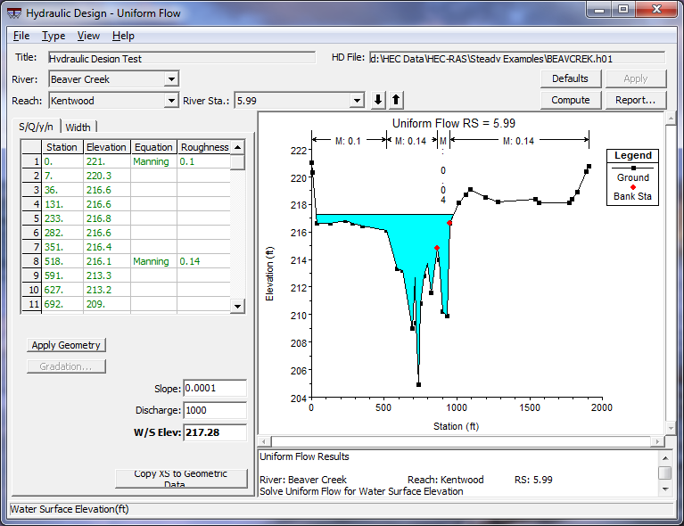
Figure 13 1. Hydraulic Design Window for Uniform Flow
Solving for Slope, Discharge, or W/S Elevation
When the S/Q/y/n tab has been selected, to calculate a slope that satisfies the uniform flow equations for the current cross section, simply enter values into the Discharge and a W/S Elev fields and press the Compute button. A value for the slope is then automatically entered into the Slope field. Likewise, for solving for discharge or water surface elevation, enter values for the other two parameters.
The roughness values are automatically taken from the geometry file, but these can be changed to better represent the bed characteristics of the cross section. In addition to changing the value of the roughness factor (in the default case, Manning's n), the function for defining roughness can be changed. To do this, click on any cell in the equation column of the table and select a function from the dropdown list. The available functions to choose from are Manning's, Keulegan, Strickler, Limerinos, Brownlie, and five grass-lined channel methods. Each of these functions is discussed in detail in Chapter 15 of the Hydraulic Reference Manual.
For the Limerinos and Brownlie functions, gradation distribution is necessary and can be entered by pressing the Gradation button. Only one gradation distribution can be used for a given cross section and should be applied only to the main channel, as these functions were developed for bed material. The Gradation window is shown in Figure 13-2. The following gradation variables are defined as the following:
- d84: The sediment particle size for which 84% of the sediment mixture is finer (mm).
- d50: The sediment particle size for which 50% of the sediment mixture is finer (mm).
- d16: The sediment particle size for which 16% of the sediment mixture is finer (mm).
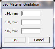
Figure 13 2. Gradation Window
The Brownlie function requires a sediment specific gravity to be entered and the Keulegan function requires a temperature to be entered. The Compute button only becomes active once all required input is entered.
To solve for a roughness value, click on and delete only one of the roughness values in the table. Only one roughness section can be solved for at a time. Make sure Slope, Discharge, and W/S Elev are specified and all other required input are entered. RAS then computes a Manning's n value to satisfy the uniform flow equation for the portion of the cross section that is desired. Then, the roughness value is back-calculated to match the selected roughness function. Only Manning, Keulegan, and Strickler functions can be used to solve for roughness, since the other functions do not have a representative roughness value to solve for.
Once one computation has been made, the value that was solved for will be shown in bold font. For subsequent computations, any of the four uniform flow parameters that is emboldened will be what is solved for to avoid having to delete out the value every time. Once a new parameter is deleted out, it will then be solved for and emboldened.
Solving for Bottom Width
Bottom width can be solved for the uniform flow equation only with a compound channel that is defined by the user. The compound channel may contain up to three trapezoidal templates, a low flow channel, the main channel, and the overbank channel. The bottom width of either the main channel or the overbank may be solved for. The addition or subtraction of width may be applied to right of centerline, left of centerline or equally to both sides.
When the bottom width tab is selected, the window shown in Figure 13-3 is displayed. To define the compound channel, enter the appropriate values into the compound channel table, which is located below the station elevation table. Data for the Overbank, Main, and Low Flow channels can be entered, however data for the low flow channel can only be applied if a main channel is also defined. The following variables are defined as follows:
- SSL: The side slope of the left side of the channel. Entering a value of "0" provides a vertical slope (1Vertical : __Horizontal).
- SSR: The side slope of the right side of the channel. Entering a value of "0" provides a vertical slope (1Vertical : __Horizontal).
- WL: The bottom width of the left side of the channel from the centerline of the channel to the toe of the side slope (ft or m).
- WR: The bottom width of the left side of the channel from the centerline of the channel to the toe of the side slope (ft or m).
- Height: The height of the respective channel from its invert to the top of its side slope (ft or m).
- Invert: The invert of the respective channel (ft or m).
Once the channel template data is entered, the user may plot the data by selecting Apply Geometry. When this button is selected, the channel design is shown in the plot window and entered in the station elevation table with the default roughness information. A Manning's n value of 0.03 will be applied to each of the channel templates defined. The user may then adjust the roughness values, change the roughness functions, or add more roughness change locations within the cross section on the station elevation table. Any changes made can be reapplied to the plot by pressing Apply Geometry. See Figure 13-4. If either the Brownlie or Limerinos functions are chosen, gradation data will have to be entered.
A value for the energy slope, discharge, and water surface elevation must be entered in the appropriate fields. The user can then select how to solve for the bottom width by using the dropdown boxes in the "Compute Widths" section. Either the main channel or the overbank channel can be solved for and the width can be applied to the left side of the channel (Left of CL only), the right side of the channel (Right of CL only), or equally to both (Total).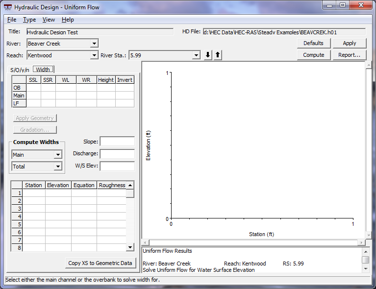
Figure 13 3. Bottom Width Calculation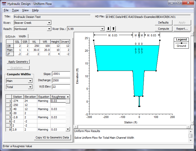
Figure 13 4. Example Bottom Width Data Entry
When all required data is entered, the Compute button will become active. The computations are constrained from creating unrealistic geometries. One example is the overbank bottom width cannot become less than the top width of the main channel. Likewise, the main channel bottom width cannot become less than the low flow channel top width. If this situation occurs within the computations, the user is notified and a course of action is suggested. However, if the top width of a lower channel becomes greater than the bottom width of the channel above it within the calculations, the program automatically increases the upper channel's bottom width to compensate.
When a solution is obtained, the new widths are updated in the compound channel table, the station elevation table and the plot.
Applying Uniform Flow Data to the Geometry File
The resulting cross section, displayed in the plot window can be added to the existing geometry data by clicking on the "Copy XS to Geometric Data" command button. The following window will appear: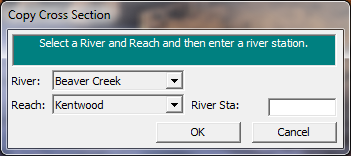
Figure 13 5. Copy Cross Section Window
Enter in the river station you want this cross section to be applied to. If the selected river station already contains a cross section, RAS will ask if you want to copy over it. If there is no cross section at the entered river station, RAS will automatically adjust the distances between the new cross section and its adjacent ones. Make sure that once the new cross section has been copied to the geometry, appropriate values for the bed elevations are reentered. This can easily be done by selecting "Adjust Elevations…" in the Option menu of the Cross Section Data window.
Saving Uniform Flow Data
To save the uniform flow data, click on File…save. This will add all pertinent data from all the HD Functions to an ascii file with the extension *.h##. The content of this file can easily be read within any word processing program.