Download PDF
Download page Performing Channel Design/Modifications.
Performing Channel Design/Modifications
The channel design/modification tools in HEC-RAS allow the user to perform a series of trapezoidal cuts into the existing channel geometry or to create new channel geometry. The current version of HEC-RAS has two tools for performing channel modifications. These tools are available from the Tools menu of the Geometric Data editor and are labeled Channel Design/Modification and Channel Modification (original). The tool labeled Channel Design/Modification is a new tool for HEC-RAS as of version 4.0. The tool labeled Channel Modification (original) is the original channel modification tool developed for HEC-RAS. The original channel modification tool has been left in HEC-RAS for those user's who may prefer this tool to the new one. Both channel modification tools will be described in this chapter. In general, these tools are used for planning studies, but it can also be used for hydraulic design of flood control channels.
This chapter does not cover the concepts of stable channel design. This software is designed to evaluate the hydraulics of various channel modifications. It is up to the user to ensure that any channel modification will not cause further scour of the channel bed and banks. Discussions on stable channel design can be found in many hydraulic text books, as well the Corps Engineering Manual "Hydraulic Design of Flood Control Channels" (USACE, 1991).
This section discusses: general modeling guidelines for using the channel modification option; how to enter the necessary input data; performing the channel modifications; and how to compare existing condition and modified condition results.
General Modeling Guidelines
In order to perform a channel modification analysis, the user should first develop a hydraulic model of the existing river reach containing the area in which the channel modification will be analyzed. This model should include several cross sections downstream from the study reach, such that any user defined downstream boundary condition does not affect the hydraulic results inside the channel modification region. The model should also include several cross sections upstream of the study reach, in order to evaluate the effects of the channel modification on the water surface profile upstream.
Once a model of the existing river system is completed, the user can use the Channel Modification (old tool) or Channel Design/Modification tools to perform trapezoidal cuts and fills into the existing geometry. Once the user has performed all of the desired channel modifications, then the modified geometry data is saved into a new geometry file. The user can then create a new plan, which contains the modified geometry and the original flow data that was used under the existing conditions plan. Computations can then be performed for the modified condition, and the user can compare the water surface profiles for both existing and modified conditions.
The Channel Modification (original) Options
- Multiple trapezoidal cuts (up to three)
- Independent specification of left and right trapezoidal side slopes
- Ability to change the Manning's n value for the trapezoidal cut
- Separate bottom widths for each trapezoidal cut
- Ability to set new channel reach lengths
- Multiple ways of locating the main channel centerline
- User can explicitly define the elevation of the new channel invert, or it can be based on the original channel invert, or it can be based on projecting a slope from a downstream cross section or an upstream cross section
- The centerline of the trapezoidal cut can be entered directly, or it can be located midway between the original main channel bank stations
- Option to fill the existing channel before performing cuts
- Cut and fill areas and volumes are computed
Entering Channel Modification Data
Within HEC-RAS, the data for performing a channel modification analysis are entered from the Geometric Data window. The channel modification data are stored within the geometry file of the base geometric data (the geometric data set in which the channel modification is being performed on).
To bring up the Channel Modification Data window, select Channel Modification (original) from the Tools menu of the Geometric Data window. When this option is selected, a Channel Modification window will appear as shown in the figure below (except yours will not have any data in it the first time you bring it up).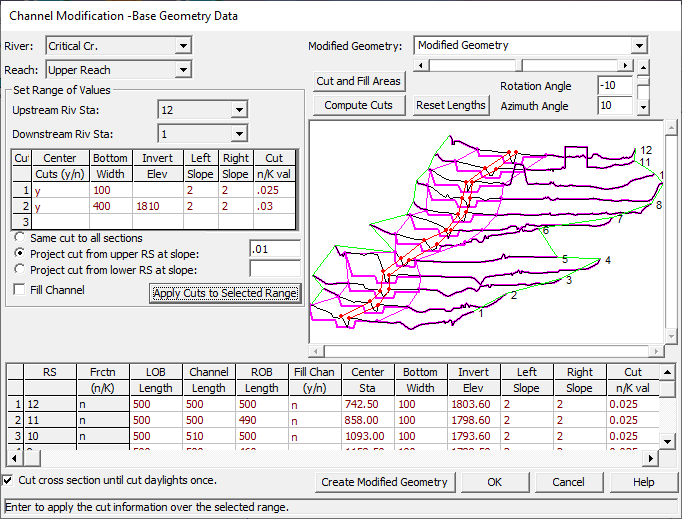
Channel Modification Data Editor
As shown in the figure above, there are several pieces of data that the user must enter in order to perform a channel modification analysis. The editor is divided into three separate areas. The top portion of the window contains selection boxes for the River and Reach; titles for the base geometry file and the modified geometry file; buttons for performing the cuts and viewing cut and fill volumes; and controls for rotating the graphic. The middle portion of the window contains a data input area for entering channel modification information over a range of cross sections, as well as a graphic of the cross sections that are being modified. The bottom portion of the window contains a table that lists the channel modification data for all of the cross sections in the selected Reach of a particular River.
The first step in performing a channel modification is to select the River and Reach in which you want to perform the analysis. This is accomplished from the River and Reach selection boxes in the upper left corner of the window. The next step is to select a range of cross sections in which you would like to perform a channel modification. This is accomplished by first selecting a cross section from the Starting Riv Sta box and then from the Ending Riv Sta box. Once this is done, all of the cross sections within the range of the specified starting and ending river stations will appear in the graphic on the right. The next step is to specify the channel modification data that you would like to apply to this range of cross sections. This is accomplished by entering information into the table contained in the "Set Range of Values" area of the window. This table allows the user to enter information for up to three cuts, which can then be applied to the selected range of cross sections. The information contained in this table is as follows:
Center Cuts (y/n): This column in the table is used to define how the trapezoidal cuts will be centered within the existing cross section data. If the user enters a "y" in this column, then that particular cut will be centered between the existing cross-section main channel bank stations. When all of the cut information is entered, and the Apply Cuts to Selected Range button is pressed, the program will automatically fill in the center stationing of the trapezoidal cuts in the lower table. If an "n" is entered, then it is up to the user to specify the center stationing for each cross section, and each cut, in the table at the bottom of the window.
Bottom Width: This column is used for entering the bottom width of the trapezoidal cuts. If this column is left blank, it is assumed that the bottom width will be zero. The user always has the option of directly entering the bottom width for each cross section in the table at the bottom of the window.
Invert Elevation: This column is used to specify the invert elevation of the trapezoidal cuts. If this column is left blank for a particular cut, then it is assumed that the invert elevation of that trapezoidal cut will be set equal to the invert elevation of the existing channel. If the user wants to have invert elevations that are not equal to the existing channel inverts, then they must enter elevations into this column and select one of the slope projection options below this table. The user has the option to use the specified invert elevations for each of the cross sections in the selected range; or they can enter elevations for the most upstream cross section and have the other invert elevations computed by projecting the cuts on a constant slope; or the elevations entered can be applied to the most downstream cross section of the range, and all others will be computed by projecting a user specified slope upstream.
Left Slope: This column is used to specify the slope of the left bank for each of the trapezoidal cuts. The slope is entered in units of horizontal distance to one unit in the vertical. (e.g., a value of 2 means the left bank slope will project 2 feet horizontally for every 1 foot vertically).
Right Slope: This column is used to specify the slope of the right bank for each of the trapezoidal cuts. The slope is entered in units of horizontal distance to one unit in the vertical. (e.g., a value of 2 means the right bank slope will project 2 feet horizontally for every 1 foot vertically).
Cut n Val: This column is used to specify the new Manning's n value to be applied to each of the trapezoidal cuts. If this column is left blank for any cut, then the existing n values will be used for that cut.
Once this table has been filled out, the user must select one of the three slope projection options listed below the table. The three options are:
Same Cut to all sections: If this option is selected, then the channel modification data entered into the table will be applied to all of the cross sections in the selected range.
Project cut from upper RS at slope: When this option is selected, the invert elevations that were entered into the table will be applied to the most upstream cross section in the selected range. The invert elevation of all of the other cross sections will be based on projecting a user entered slope from the most upstream cross section to each cross section downstream. The user must enter a slope when this option is selected. The elevations of each cross sections trapezoidal cuts are based on the user entered slope times the distance that each cross section is from the most upstream cross section. The distance is the cumulative main channel reach length for each of the individual cross sections.
Project cut from lower RS at slope: When this option is selected, the invert elevations that were entered into the table will be applied to the most downstream cross section in the selected range. The invert elevation of all of the other cross sections will be based on projecting a user entered slope from the most downstream cross section to each cross section upstream. The user must enter a slope when this option is selected. The elevations of each cross section's trapezoidal cuts are based on the user entered slope times the distance that each cross section is from the most downstream cross section. The distance is the cumulative main channel reach length for each of the individual cross sections.
A final option that can be applied to the selected range of cross sections is the Fill Channel option. When this option is turned on, the main channel of the base cross-section data will be filled before any of the trapezoidal cuts are applied. The main channel is filled to an elevation equal to the elevation of the lower of the two main channel bank stations.
Once the user has filled in all of the desired data in the "Set Range of Values" data area, then the Apply Cuts to Selected Range button should be pressed. When this button is pressed, the lower table is filled with the specific information that will be applied to each of the cross sections in the selected range. The cut information is then applied to each of the cross sections, and the graphic is updated to show both the existing cross section and the modified cross sections.
The user has the option of entering and modifying the channel modification data directly in the table at the bottom of the window, or they can use the "Set Range of Values" data area to apply a set of channel cut properties to a range of cross sections (this can be done several times for different ranges of cross sections within the reach).
A final option available to the user is Cut cross section until cut daylights once. This is a global option that will be applied to all of the channel modification data. When this option is selected, as the program performs the cutting of the trapezoidal channel, the left and right banks of the channel will start at the bottom of the trapezoid and cut through the ground until they reach open air, then the cutting will stop. If this option is turned off, the left and right banks of the trapezoid will be projected to infinity, continually cutting any ground that lies above them.
Performing the Channel Modifications
Once all of the desired channel modification data are entered for a reach, the user should press the Compute Cuts button at the top of the graphic. When this button is pressed, all of the channel modification data from the lower table is applied and the graphic is updated to reflect the new cut information. The user can continue to modify the data and press the Compute Cuts button as many times as is necessary to get the desired cuts. The cut information is always applied to the base geometry data.
Once the user has completed the desired channel modifications for the reach, they can view the cut and fill quantities by pressing the Cut and Fill Areas button. When this button is pressed, a window will appear as shown in the figure below.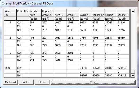
Channel Modification Cut and Fill Quantities
The cut and fill quantities table shows the cut, fill, and net areas and volumes for each of the individual cross sections, as well as the totals for the reach. The table shows the cut and fill quantities that were necessary in order to transform the existing cross-section data into the modified cross-section data. The areas and volumes are provided in the categories of left overbank, main channel, right overbank, and total. These categories are based on the main channel bank stations of the base geometry data. The volumes listed at a particular cross section, represent the volume between that cross section and the next downstream cross section. The total volume and area at a particular cross section is the sum of the left overbank, main channel, and right overbank quantities for that individual cross section only. Total volumes for the entire reach are listed at the bottom of the table. The Cut and Fill Quantities table can be printed, sent to a file, or copied to the clipboard, by pressing the desired button at the bottom of the window.
The channel modification option has been set up to work with one Reach of the model at a time. If the user needs to perform channel modifications to more than one reach of a multiple reach model, they can simply select a new reach at any time. While the information in the tables and the graphic only show a single reach, the channel modification information is stored for all of the reaches.
Once the user has finished all of the desired channel modifications, for all of the desired reaches, a new geometry file should be created for the modified geometry. To create a modified geometry file, the user must enter a title for the modified geometry file in the upper right hand side of the window. Once the new geometry file title is entered, the file can be created by pressing the Create Modified Geometry button at the bottom of the window. When this button is pressed, a Save Geometry Data As window will appear. The user has the options to change the directory in which the geometry file will be stored, change the name of the geometry file title, or select an existing geometry file to over write. Once the user has decided on a title and a directory, the OK button can be pressed to save the modified geometry to the hard disk. However, the original geometry file is still the one that is in memory. If the user wants to work with the new modified geometry file, they will need to open it from the Geometric Data Editor window.
Note: the data entered into the channel modification editor is saved as part of the base geometry file (i.e., it is not saved with the modified geometry file). This allows the user to open the base geometry file and recreate the modified geometry. In order for this data to be saved, the user must select Save Geometry Data from the file menu of the geometric data editor, after they have entered the channel modification data.
The Channel Design/Modification Tool Options
- Identifying river reach channel designs by Alternative
- Independent specification of cuts for the left and right overbank (width, depth, side slopes, and Manning's n values)
- Ability to set new channel reach lengths
- Identifying separate channel cut data in a Template
- User can explicitly define the elevation of the new channel invert, or it can be based on the original channel invert, or it can be based on projecting a slope from a downstream cross section or an upstream cross section
- The centerline of the trapezoidal cut can be entered directly, or it can be located midway between the original main channel bank stations
- Option to fill the existing channel before performing cuts
- Cut and fill volumes are computed
The general concept behind the Channel Design/Modification tool is that a user develops a cross-section Template. The Template may then be applied to existing cross-sectional data (as performed historically in HEC-RAS) to perform Channel Modifications. The Template may be also be used in Channel Design to create new cross sections on a river reach.
Entering Channel Modification Data
Within HEC-RAS, the data for performing channel modifications are entered from the Geometric Data window. The channel modification data are stored within the geometry file of base geometric data (the geometric data set on which the channel modifications are being performed).
To bring up the Channel Design/Modification data window, select Channel Design/Modification from the Tools menu of the Geometric Data window. When this option is selected, a Channel Design/Modification window will appear, as shown in the figure below.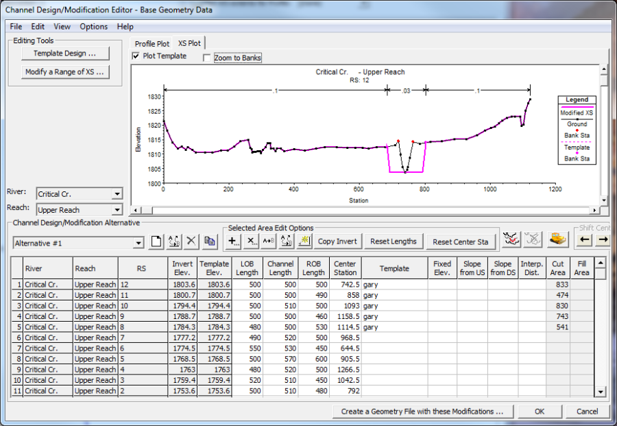
Channel Design/Modification data editor.
As shown in the figure above, there are several pieces of data that the user must enter to perform channel modifications or create new cross sections. The editor is comprised of two main components: data entry and data visualization. The table at the bottom of the window displays a summary of all modifications (by "Alternative") that will be made to the selected River and Reach when new geometry is created. Several buttons are provided to allow the user to quickly enter data into the summary table. As data is entered into the editor the graphics plot in the upper portion of the window will be updated. Note that there are different graphic plots and each graphic plot may have more than one way to display data. Once data has been specified for the cross sections to be modified, the user may create a new geometry file by pressing the Create a Geometry File with these Modifications … button.
Identify the River and Reach to perform the channel modification and select or create a new Channel Design/Modification Alternative. This will update the channel modifications summary table, displaying the all of the cross sections for the selected River and Reach and cut data for the specified Alternative. You then have access to directly change the data in the table provided.
Alternatives
The Channel Design/Modification Alternative is used to group a set of cross section cut data. The default name for an Alternative is "Alternative #1", but may be renamed as desired. To the right of the Alternative select list box are buttons that allow you to Create, Rename, Delete, or Copy an Alternative. These functions are also available from the Options menu.
All of the data provided in the Channel Design/Modification Alternative data table is associated with the Alternative. Data that is displayed in black has been saved to the Alternative while that data shown in red has not. Switching between multiple alternatives will automatically save the data currently displayed in the Alternative.
When the summary data table showing the cross section cut data is loaded, some of the data comes from the existing cross sections and some comes from the modification data. Some of the data may be edited while the grayed out fields are set or computed internally. Manual entry of data may be performed on a cell-by-cell basis or over a selected range. Further, the Selected Area Edit Options may be used to automate data entry. Tool tips are provided for each of the buttons: Add, Multiply, Set, Replace, Interpolate, Copy Invert, Reset Lengths, and Reset Stations. The table fields and their use are described below.
River – This column identifies the River that the cross section is location on. It is not editable by the user.
Reach – This column identifies the Reach that the cross section is location on. It is not editable by the user.
RS – This column identifies the River Station of the cross section and is not editable.
Invert Elev. – This column displays the computed lowest point in the existing cross section. It is not editable by the user.
Template Elev. – This is the elevation at which the cross section Template will be applied. While this column is not directly editable, it is set based on the values applied in the Fixed Elev., Slope US, or Slope DS columns. By default the values in this column are copied from the Invert Elev. column.
LOB Length – This is the Reach Length for the Left Overbank. The default value displayed comes from the cross-sectional data.
Channel Length – This is the Reach Length for the main Channel. The default value displayed comes from the cross-sectional data.
ROB Length – This is the Reach Length for the Right Overbank. The default value displayed comes from the cross-sectional data.
Center Station – This is the station at which the center of the cross-section Template will be applied. The default value is computed as the center of the existing cross section between the main channel bank stations.
Template – This is name of the cross-section Template. The Template name is selected from a drop down list in the table. The user must create a Template using the Template Design editor prior to selecting one in the table. The Template contains several parameters not displayed in the summary table.
Fixed Elev. – This is the elevation at which the bottom of the Template will be applied to the cross section as fixed by the user. This value is copied to the Template Elev. column.
Slope US – The Template Elev. is computed using the Slope projected from the Upstream XS and the upstream Channel Length.
Slope DS – The Template Elev. is computed using the Slope projected from the Downstream XS and the current Channel Length.
Interp. Dist. – The maximum interpolation distance between the current cross section and the next cross section downstream. Leaving the Interp. Dist. field blank means that no interpolation is desired.
Transition – The name of the Transition type that will be applied between cross sections. Default is linear.
Cut Area – This column displays the computed Cut Area for the cross section.
Fill Area – This column displays the computed Fill Area for the cross section.
Template Design
The Cross Section Template Design editor, shown in the figure below, is used to create a cross-section Template to modify existing cross sections. Template data are saved with the geometry file, so that it may be used repetitively to perform channel modifications on various cross sections. The Template Design editor provides the user with tools to manage templates by name, edit the template cuts and properties, and visualize the resulting template. The user has two methods available for creating a template. One template option is a User Entered Table of DX, DY, Slope, and Mannings n values for the left and right side of the template. The other template option is a Simple Trapazoid. The simple trapezoid template option allows the user to enter a channel depth, bottom width, side slope, and Manning's n value to create the trapezoid.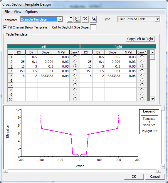
Cross-Section Template Design editor with User Entered Table option selected.
Prior to entering Template information, the user must create a new Template. Templates are managed from the Options menu or using the buttons shown below the menu bar at the top of the editor. The Options available from the Template Design editor include New, Rename, Delete, and Copy. New, Rename, and Copy will prompt the user for a new Template name. Delete will remove the currently active Template from the geometric data.
If the user has selected the User Entered Table option for creating a template, cut data are entered into the table for the Left and Right side of the template separately. Data is entered starting from the centerline of the template and moving out towards the overbanks (i.e. the first line in the table is information that starts at the centerline of the template and goes to the left and right). Data that defines the shape of the template includes DX, DY, Slope, N Val, and main channel Bank location for the left and right sides of the template. Other data to consider is whether to Fill Channel Below Template and the value to Cut to Daylight Side Slope (horizontal to 1 vertical).
DX – This column specifies the length of the cut in the horizontal direction over the corresponding elevation change of DY.
DY – This column specifies the change of elevation over the length specified in corresponding DX.
Slope – This is the slope of DY/DX. It will be calculated if DX and DY are specified. If only DX (or DY) is already specified, the Slope may be entered to calculate DY (or DX).
N Val – This is the Manning's n value to be applied to this portion of the template cross section.
Bank? – This column is used to specify the hinge point used to establish the main channel Bank Station for the template. Only one row per side may be selected for the bank station.
Fill Channel Below Template – If checked, this option will fill the main channel of the cross section prior to applying the Template.
Cut to Daylight Side Slope – This is the slope (horizontal to 1 vertical) to apply a cut above the last point in the template. The default (blank) will result in vertical wall after the last point in the template. (e.g. a value of 2 means that the cuts for the left and right bank beyond the last point of the template will be projected to the existing cross section 2 units horizontally for every 1 foot vertically).
Copy Left to Right – This button is used to copy the information specified for the left side of the template to the right side. This is a convenience function that can be used when the right side of the template is a mirror image of the left side.
If the user has selected the Simple Trapezoid option for the template type, then the template editor will look like what is shown in Figure 12-5. When this type of template is picked, the user enters a channel Depth; Bottom Width; Side Slope; and Manning's n Value for the simple trapezoid. Multiple trapezoidal templates can be developed and saved under different names, and then applied within a given Channel Design/Modification Alternative.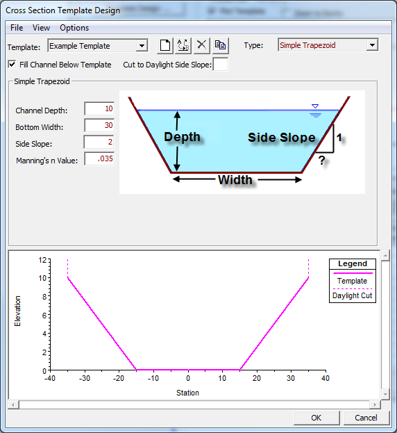
Template editor with Simple Trapezoid option selected.
Modify a Range of XS
Channel design/modification information may be entered to a range of cross sections using the Modify a Range of XS editor, shown in the figure below, rather that entering the data in the table provided on the main Channel Design/Modification editor. This editor is appropriate when you want to create a channel within one River Reach by applying the same Template to a number of cross sections at a given slope. A Template should have been defined prior to entering the editor, but the Template Design button allows the user access to the Template Design editor.
The intended use of this editor is to allow the user to apply a template over an existing set of cross sections; however, the Add New XS button allows the user to specify a new cross section at a river station along the specified River Reach. The new cross section will be created only when the user presses the Create a New Geometry File with these Modifications button. The user is not provided with the option to specify any cross-sectional properties such as station-elevation data, Manning's n value data, or downstream reach lengths. Therefore, cross sections should be added to the geometry in this manner sparingly.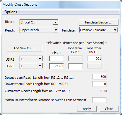
Apply channel modifications to a range of cross sections.
When the Modify a Range of Cross Sections button is pressed, the window will initially open with the current River and Reach selected, but the user may select any River Reach currently in the data set. The user will then select the Template to apply to the specified reach. If a Template has not yet been defined the user can access the template Design editor through the button provided.
Cross sections over which the Template information should be applied are selected using the US RS (Upstream River Station) and DS RS (Downstream River Station) list boxes. All cross sections in the exiting geometry, as well as those "new XS" locations that have been added, will be available to select. As a river station is selected, elevation data and reach length data on the form will be updated.
Each time a river station is selected from the US RS or DS RS list box the corresponding elevation data will be updated from the information on the main Channel Design/Modification editor. After selecting the US and DS river stations fix the elevations for the Template invert at the river stations. This may be done by entering an elevation value in the Elev. field or by entering a slope value. If one of the slope fields is chosen, the invert elevation for the river station will be computed using the reach length to the cross section (US or DS) and the cross section's invert elevation. If both elevations are specified for the US and DS river station the Template will be applied to the range of cross sections on constant slope between the river stations.
Performing the Channel Modifications
Once a design Template has been specified for a given cross section, a preview of the channel as modified is displayed in the XS Plot graphic area. The XS Plot will display the cross section of the row that is currently active in the summary cut table at the bottom of the window.
As shown in the figure below, the original cross section is displayed in black, while the new cross section is shown in magenta. Then Manning's n value data that is furnished at the top of the plot are the values associated with the new, modified cross section. The new bank stations will also be shown in magenta. The Plot Template option will toggle on/off the entire channel design Template, displaying the Template as a dashed line.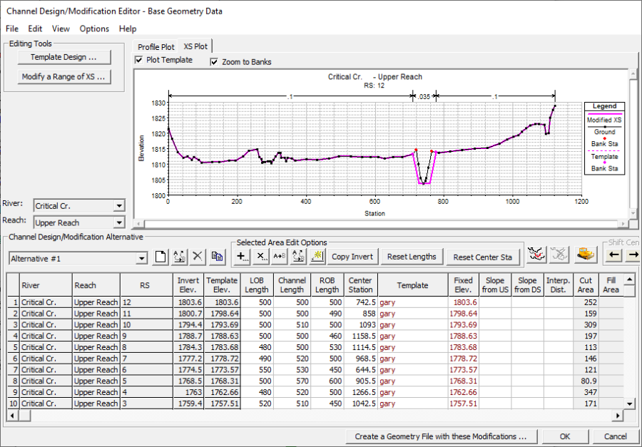
Preview of a modified cross section in the Channel Design/Modification editor.
New (interpolated) cross sections may also be inserted into the channel modification editor. They will appear as if they are part of the original geometry (in the design/modification editor) to allow you to apply templates; however, as shown in the figure below, the row will be grayed out to indicate the cross section doesn't actually exist. 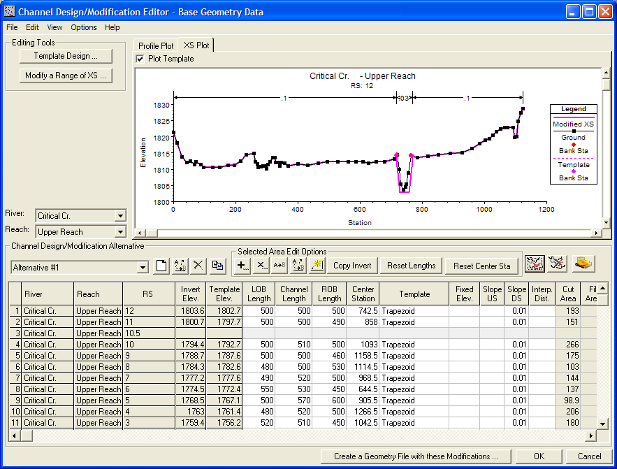
A new cross section is added at River Station 10.5 into the Channel Design/Modification editor.
To insert a cross section, select the ![]() (Add new design cross section) button. You will be asked to enter a river station for the new cross section, just like adding a cross section in the geometric editor. You are then required to input reach length data to allow HEC-RAS to interpolate the cross section from existing data. (You will also need to adjust the downstream reach lengths for the upstream cross section.) Entry of the Template Elevation into the Fixed Elev. field, inspection of the Center Station for placing the template, and selecting a Template will also be required. To remove and inserted cross section, select the
(Add new design cross section) button. You will be asked to enter a river station for the new cross section, just like adding a cross section in the geometric editor. You are then required to input reach length data to allow HEC-RAS to interpolate the cross section from existing data. (You will also need to adjust the downstream reach lengths for the upstream cross section.) Entry of the Template Elevation into the Fixed Elev. field, inspection of the Center Station for placing the template, and selecting a Template will also be required. To remove and inserted cross section, select the ![]() (Remove design cross section) button. This button is only available when an inserted section is selected in the table, as shown in in the figure below.
(Remove design cross section) button. This button is only available when an inserted section is selected in the table, as shown in in the figure below. 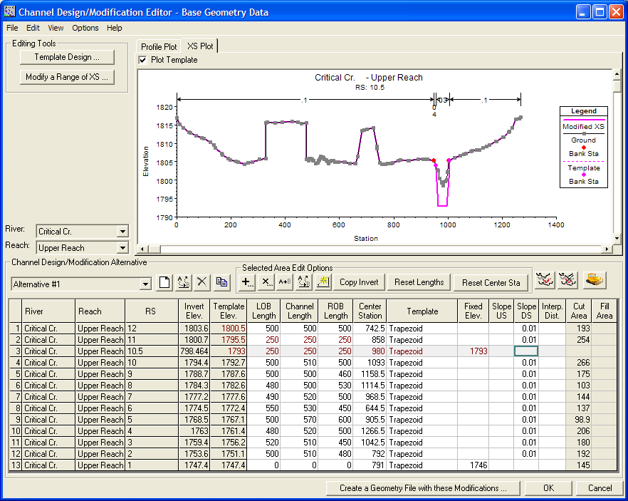
Channel design/modification editor with an inserted cross section with completed data.
Cut and Fill areas are also computed for each cross section. Detailed cut and fill data are available from the Summary Cut and Fill data table. The Cut and Fill Summary Table is accessible by pressing the ![]() button. There are several options for displaying the Cut and Fill Volume and Area information. A summary of Volumes is shown in the figure below. If any of the Area options are selected, information for the Upstream (U/S) and Downstream (D/S) cross sections will be displayed. If a section is modified back in the Channel Design/Modification Editor, the Refresh Table button can be used to recomputed the Cut/Fill information and update the summary table.
button. There are several options for displaying the Cut and Fill Volume and Area information. A summary of Volumes is shown in the figure below. If any of the Area options are selected, information for the Upstream (U/S) and Downstream (D/S) cross sections will be displayed. If a section is modified back in the Channel Design/Modification Editor, the Refresh Table button can be used to recomputed the Cut/Fill information and update the summary table.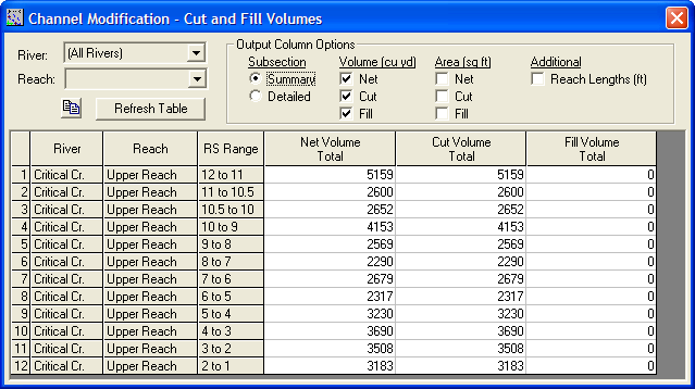
Summary Cut and Fill information for the channel configuration.
Once the desired channel modification data have been entered for all of the desired reaches, a new geometry file must be created. A new geometry file with the Template data applied is created by pressing the Create a Geometry File with these Modifications button. An intermediate window will appear to allow the current geometric data set to be saved.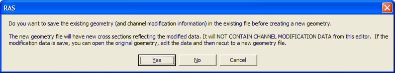
The new geometry will not contain the channel modification data.
The user will then be prompted to enter a new title for the geometry file that is going to be created. If a title is entered that has already been used for a geometric data set, you will be prompted to overwrite the existing data file. Note that the data entered into the Channel Design/Modification editor is saved with the base geometry file and is not saved with the modified geometry file. This allows the user to open the base geometry file and recreate the modified geometry.
Comparing Existing and Modified Conditions
Once a modified geometry file is created, the user can create a new plan that will incorporate the modified geometry and the previously defined flow data. This is accomplished by first opening the modified geometry file from the Geometric Data window. The next step is to open the Steady Flow Analysis window and create a new Plan. Creating a plan is accomplished by selecting New Plan from the File menu of the Steady Flow Analysis window. Once a new plan is created, the computations can be performed.
After the water surface profile computations have been performed for the modified channel conditions, the user can compare the results of the existing and modified conditions on any of the graphics and tables. An example cross-section plot of the two plans is shown in the figure below - the geometry of the modified and existing conditions, along with the computed water surface elevations from both the existing and modified plans. To display the geometry and results from more than one plan on a graphic, the user can select Plan from the Options menu on any of the graphics. At the top of the plan selection window, turn on the option that says "Compare Geometry As Well As Output." Select the two plans to be viewed and hit the OK button. The geometry and output for both plans will be displayed.
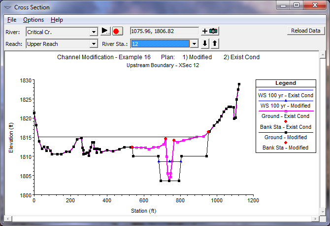
Existing and Modified Geometry and Water Surface Elevations.
In addition to graphical output, the user can review the computed results from both plans in a tabular form. The figure below shows the computed results for both plans in Standard Table 1 of the Profile Output table.
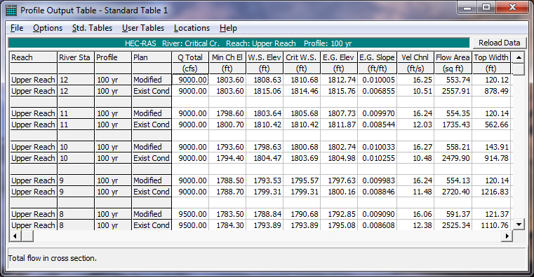
Existing and Modified Geometry and Water Surface Elevations.