Overview
Bridges can be modeled in 2D Flow Areas using two approaches: (1) Simplified 1D/2D Bridge Modeling, and (2) Detailed Bridge Modeling. The simplified bridge modeling approach is applicable for all types of flows through bridges but is not intended to capture the details of the bridge hydraulics through the bridge. It's purpose is to capture the overall head losses from the bridge. It can also be applied with any of the 2D flow solvers including the Diffusion Wave Equation solver. In the detailed bridge modeling approach, the bridge piers are specified in the terrain since it cannot yet utilize the bridge deck and pier geometry specified in the SA/2D Connection. It also cannot simulate pressured flow with or without overtopping. Future versions of HEC-RAS will be able to simulate pressured flow and overtopping.
Simplified 1D/2D Bridge Modeling
In the first approach, the bridge is setup using an internal SA/2D Connection, and the bridge geometry and parameters are specified similar to how bridges are entered for 1D bridge modeling. The figure below shows an example layout of an internal SA/2D connection with a bridge.
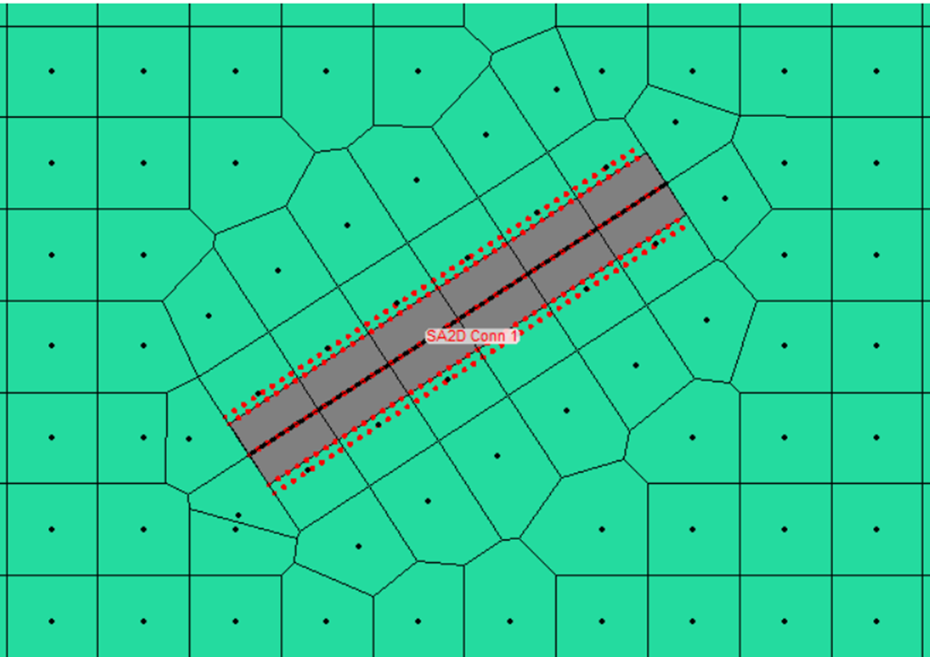
Figure 1. Example 2D bridge layout in the Geometric Data editor.
The SA/2D connection is enforced as a breakline and has faces running along the bridge centerline. The connection also shows 1D bridge cross-sections upstream and downstream of the bridge as dotted, red lines. The bridge curves are computed using the water surfaces defined on 1D bridge cross-sections. For this reason, it is important to utilize a grid resolution which is consistent with the cross-section spacing. The mesh resolution should be such that the cell computation points are at or close to the cross-sections.
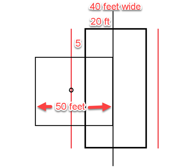
In the example shown in the figure below there is a 40-ft bridge deck, with 5-ft upstream and downstream distances from the bridge centerline to the upstream and downstream cross-sections are 25 ft. Therefore, an appropriate mesh resolution should be 50 ft.
The steps for adding a 2D bridge are:
- Draw a centerline for the bridge opening/embankment using the SA/2D Area Connection tool
- Bridge centerline is drawn left to right looking downstream.
- Develop an appropriate mesh (cell size and orientation) for the bridge.
- Use the structure mesh controls (cell size and enforcement). Some hand editing may be required depending on the bridge and what else is near the bridge (i.e. levee, another bridge, railroad tracks, road, etc…).
- Enter the bridge data.
- Deck/roadway; distance from upstream bridge deck to outside cross section piers; abutments; bridge modeling approach; Manning’s n values for the 1D bridge cross sections; and hydraulic tables controls (HTAB) into the SA/2D Area Connection editor.
- Pre-process the geometry in order to create the bridge curves.
- Review the bridge family of rating curves for hydraulic accuracy.
- Run the model and review the results.
- Make any necessary changes to the data in order to improve the results.
Note
The detailed bridge modeling approach does NOT automatically modify the terrain to account for the bridge geometry. Therefore, the user must make sure the bridge geometry with the exception of the bridge deck is included in the terrain.