Download PDF
Download page 2D Unsteady Flow Floodway Encroachment Analysis.
2D Unsteady Flow Floodway Encroachment Analysis
2D Floodway Encroachment analyses can be performed with the unsteady flow computations module within HEC-RAS. The 2D approach for encroachment analysis utilizes Encroachment Regions within RAS Mapper to establish left and right encroachment locations for 2D unsteady flow modeling.
When performing a floodway encroachment analysis, the base information should be consistent, meaning that the geometry, flow, and plan data should all be identical. Identical data allows for a consistent evaluation of the impacts to the model results given the encroachment information. Therefore, there are some basic guidelines that should be considered.
- The geometry must be the same for both the Base and Encroached plans.
- The flow data must be the same for both the Base and Encroached plans. Normal depth, or a rating curve, is a good downstream boundary condition as it will account for the change in water surface elevations due to changes in flow conditions.
- The plan data must be the same for the Base and Encroached plans.
- The Base plan must be run prior to running the Encroachment analysis
A summary of the steps performed in 2D Unsteady Flow Floodway Encroachment Analysis is provided below.
- Create and run a base plan.
- Create Reference Lines - this will require re-running the base plan.
- Create a new encroached plan.
- Create Encroachment Regions in RAS Mapper.
- Identify the base plan in the Encroachments editor.
- Run the encroached plan.
- Evaluate the results
- Refine the Encroachment Regions.
- Evaluate, refine, run, and repeat, as necessary.
Reference Lines
Reference Lines are used to evaluate results from 2D models. To compare the base run with the encroached run, you will need to have created Reference Lines (either manually or using the auto-generation tools). Reference Lines should be created in locations where the flow is gradually varied and predominately one-dimensional. The automated tools can assist in generating Reference Lines either one at time or in bulk based on contouring the water surface elevation layer or creating them perpendicular flow based on the velocity layer.
Reference Lines must be created prior to a model simulation.
Workflow for creating individual Longitudinal reference lines from the velocity layer is listed below.
- Turn on the Velocity layer
- Turn on the Plot Option to Track the Longitudinal Velocity at the Cursor
- Select the Profile of interest
- Move the cursor to the desired location
- Right-click and choose Create Reference Line

Workflow automation for creating Reference Lines is listed below.
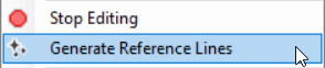
- Start Editing the Reference Lines layer
- Right-click on the Reference Lines layer and choose Generate Reference Lines
- Select the Result to evaluate

- Select the Profile to evaluate - Selecting a specific timeline is important for generating contours of velocity (picking Max will likely give poor results where flow changes dynamically because those values are a composite from multiple computation time steps)
- Select the Contour Method (Perpendicular to Velocity or by Water Surface Elevation)
- Perpendicular to Velocity uses the velocities from the computational mesh
- Water Surface Elevation uses the interpolated raster surface using the Sloping Render Mode
- Select the Sampling Method (by Water Surface Elevation or Distance Along Reference Line)
- Water Surface Elevation creates Reference Lines based on the contour interval specified (i.e. every change in 1.0ft of water surface elevations)
- Distance Along Reference Line creates Reference Lines evenly spaced along the longitudinal reference line selected in the table
- Specify the Sampling Interval for the Sampling Method
- Select the Reference Lines to sample along
- Specify the line Filter Tolerance to reduce the number on points on each reference line
- Press OK - lines will be auto-generated and added to the Reference Lines layer.
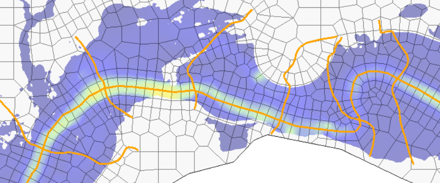
It is likely, that the auto-generated Reference Lines will not meet the desired evaluation needs. They should then be edited by the user to satisfy the objective of placing Reference Lines in highly one-dimensional locations, perpendicular to flow, and covering the expanse of the floodplain (without extraneous points). To generate additional reference lines, use the interactive tools by either contouring the water surface elevation map or the velocity map. An example of tracking the transverse velocity is shown below.
The Track Transverse Velocity at Cursor will create a line perpendicular to the velocity as you move your cursor over the velocity surface.
![]()
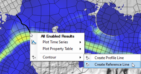
When you have identified a location to create a reference line, right-click and select the Velocity Track (Transverse) | Create Reference Line menu item and the Reference Line will be created in the base geometry group of type "Transverse".

You can create Reference Lines interactively using the WSE map and turning on the Plot Contour at Cursor plot option. After identifying the location of interest, right-click and choose the Contour | Create Reference Line menu option.
Unsteady Flow Encroachment Data
Prior to beginning the encroachment analysis, you will need to have simulated a base run and created a new encroachment plan. From the new encroached plan, you will proceed with creating the encroachment data.
For 2D unsteady flow encroachment analysis, the procedure of creating Encroachment Regions is used. It is intended that users can perform floodway encroachment analysis on 1D, 2D, or combined 1D/2D models with a mix of encroachment methods. However, for portions of the 2D model domain, Encroachment Regions are the only method to control the floodway analysis.
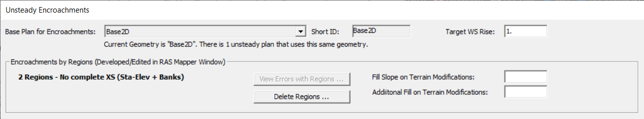
From the new encroachment plan, access to the Unsteady Flow Encroachment Editor, shown below, from the Unsteady Flow Analysis window from the Options | Unsteady Encroachment menu item. To enable the encroachment analysis, select the base plan from the "Base Plan for Encroachments" list.
A description of the parameters in the Unsteady Flow Encroachment Editor are described below.
| Parameter | Description |
|---|---|
| Base Plan for Encroachments | Base Plan used for results comparison. Choose the "Disabled - (No Encroachment Analysis)" in order to not run an encroachment analysis. |
| Target WS Rise | Max allowable water surface rise (allowable surcharge) for the encroached floodway. This value is used to (1) set the elevation comparison for the surcharge map, (2) set the elevation comparison target line in the profile plots, and (3) will be used for a fill elevation Terrain Modification for a new RAS Terrain to simulate a filling in of the floodplain at the water surface edge for 1D and 2D unsteady simulations. |
| Encroachment Regions | If Encroachment Regions (polygons) are specified in the Plan data in RAS Mapper, the polygons will be used a eliminate flow up to the specified Target Rise. If there is greater surcharge than the Target Rise it will be evident in the floodplain mapping. |
| Fill Slope on Terrain Modifications | Sloping of fill (away from the floodway) for the Terrain Modification in the new encroached RAS Terrain layer. The base elevation for the Terrain Modification is based on the Target Rise. (This option is implemented to facilitate rain on grid modelling for runoff to enter the floodplain.) This value may be set to 0. |
| Additional Fill on Terrain Modifications | Additional fill height added to the Target Rise for creating the Terrain Modification for the Encroached RAS Terrain. |
Performing Unsteady Flow Encroachment Analysis
The HEC-RAS encroachment procedure is based on previously calculated water surface elevations (base plan). Subsequent simulations utilize the base plan to compare against the encroached results. To perform floodway encroachment for a 2D model, you will need to create and refine Encroachment Regions which will control the movement of water into the floodplain fringe. The Encroachment Regions will be used to create a Terrain Modification using the Target Water Surface Rise to "fill" the floodplain fringe.
The Terrain Modification results in a new RAS Terrain and associates it with the geometry used for the floodplain encroachment analysis. Therefore, each subsequent simulation will require that new hydraulic property tables are created.
Data Preparation
Encroachment Regions are an editable layer in the Plan group. Encroachment Regions are polygons which are used to block out area by raising the terrain withing these polygons. Encroachment Regions are a fully editable data layer that may be created manually, imported from shapefile (created outside of HEC-RAS), or created with automation tools in RAS Mapper. You may wish to create a 1D HEC-RAS model and copy encroachment result from that run. In the end, the objective is to make the Encroachment Regions layer flexible to allow you to create the polygons wherever convenient.
Extending the Encroachment Regions beyond the edges of the 2D Flow Area polygons is recommended.
The basic steps to create the Encroachment Regions for a Plan is listed below.
- Open RAS Mapper
- Expand the Plans group and Encroachment Plan
- Start Editing
- Select the Regions layer

- Create encroachment polygons
- Encroachment polygons can be created manually or through automation using results maps.
- Stop Editing
Creating Encroachment Regions with Automation
To assist with establishing the floodway, RAS Mapper provides the capability to convert mapping results (from Depth*Velocity results in a base plan) to encroachment polygons. If the river system is small enough, you can use a single Profile (timestep) for use in evaluation. However, if the river is long, where peaks occur in different places at different times, you will either need to create a stored map for the Max or perform the evaluation multiple times and combine the results of the analysis (which is a more complicated process). If the river system is long, not only will peak flow and velocity happen at differing times, the depth*velocity (DV) value, used to identify less consequential conveyance portions of the floodplain, will vary throughout the river system. In such case, where you want to develop encroachment regions based on differing DV values, use the Zones layer to create individual polygons and specify the DV contouring value. The Zones layer is discussed in more detail below.
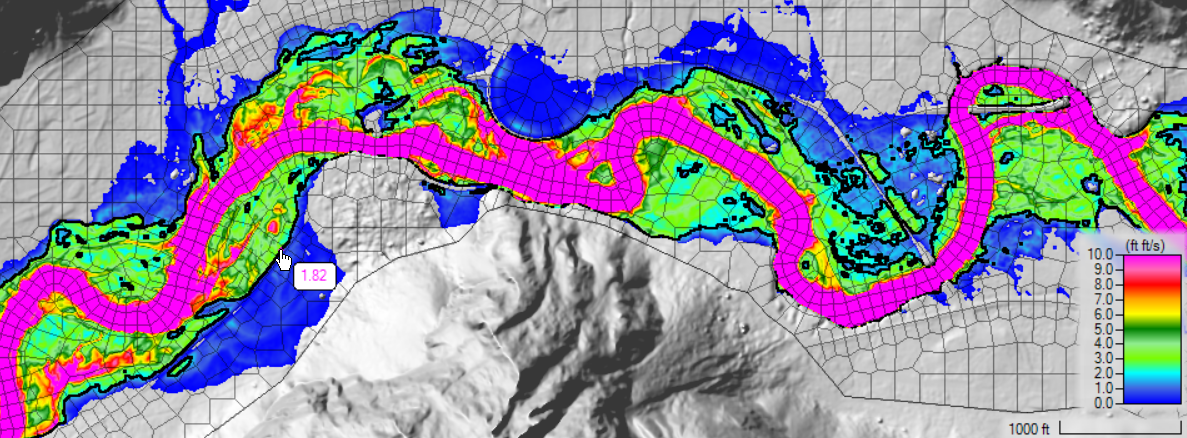
An example for creating encroachment polygons can be explained through the use of a Depth*Velocity output layer for a single profile (dynamic map). First, evaluate the results from a base plan in RAS Mapper to identify the timestep of interest. In the figure below, a DV map is shown for one of the timesteps in the unsteady simulation for the base plan. Use the cursor to identify a DV threshold that is of interest. There is a plot option on the layer that will contour the map based on the value at the cursor.
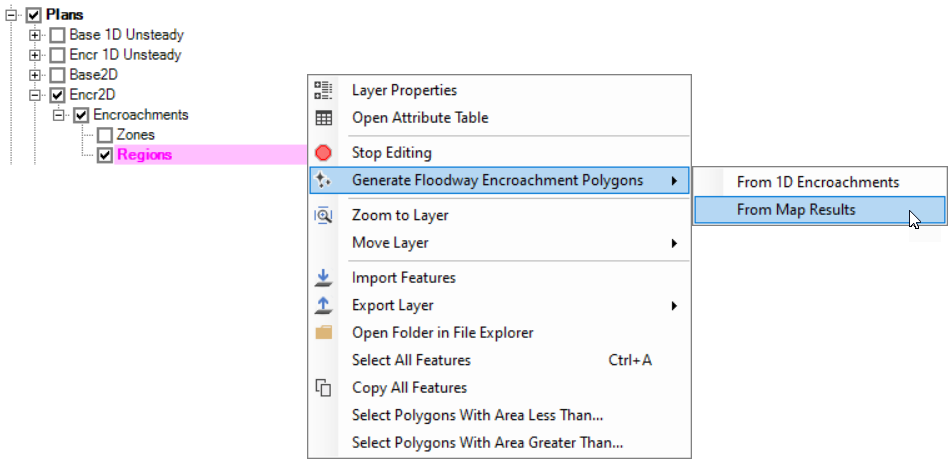
Once an initial value for the floodway has been identified, you can use tools to auto-generate the encroachment polygons. The procedure for creating encroachment polygons from existing map results is outlined below.
- Start Editing the Encroachments layer.
- Optional. Define differennt floodway zone polygons for the Zones layer.
- The Zones layer allows for contouring the map layer at different contour intervals throughout the floodplain.
- Select the Generate Floodway Encroachments Polygons | From Map Results menu item.
- Provide information in the Generate Floodway Encroachment Polygons dialog.

- Select the Base plan/result.
- Select the Map Layer. Only layers in the selected plan are available.
 If you have defined Zones, you most likely will want to use a DVmax raster. Otherwise, you will need to have previously selected a Profile of interest for display on the map and the Base Plan.
 - Provide Resample Cell Size (if desired). Resampling the map results will lead to more approximate answers, however, the computation of the encroachment polygons will be faster with a larger cell size
- Provide a Contour Value (if a Zones layer has been defined, specify a contour per Zone).
- A polygon will be created encapsulating all values greater than the contour value.
- The polygon will be intersected with the modeling domain (2D Mesh).
- The interior polygon (the river floodway) will then be deleted leaving the Encroachment Regions.
- Provide a Filter Tolerance (Optional). If specified, the Encroachment Regions will have a point filter applied that looks at three consecutive points, removing the middle point if it falls within the tolerance. (A larger value will remove more points than a smaller value.)
- Provide a Simplify Tolerance (Optional). If specified, the Encroachment Regions will be buffered in and then buffered out, in an attempt to smooth the polygons (removing "peninsulas" and "islands"). Points are then filtered using the Filter Tolerance.
- Further refinement is usually necessary. The user should edit the encroachment regions to smooth them out, remove areas that should not be encroached, and possibly break up regions into more zones (see Zones discussion below).
- Stop Editing and Save edits

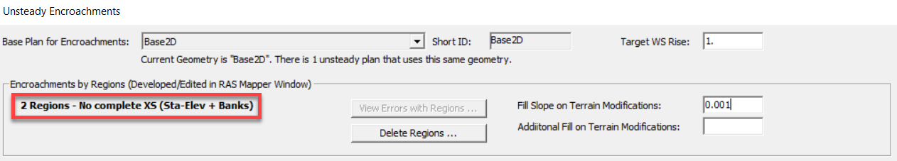
The Unsteady Flow Encroachment Editor will indicate the presence of Encroachment Regions, as shown below.
Zones
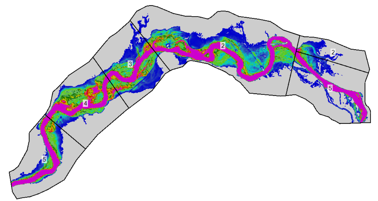
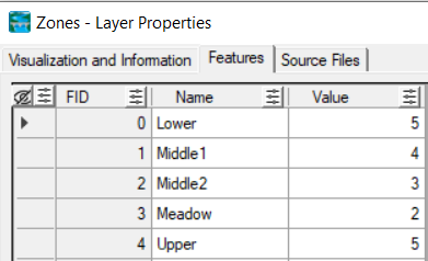
The Zones layer is used to specify contour values for different regions of the floodplain for the auto-generation of encroachment Regions. This is necessary for automating the creation of encroachment regions when the characteristics of the floodplain can change throughout the system leaving a single contour value inadequate (slower velocities are typical in more shallow-sloped floodplains typical of the lower reaches in a river, when compared with headwater reaches, and may allow for a lower D*V product). As shown in the figure below, multiple zone polygons have been created and provided differing contour values (shown) based on the floodplain characteristics.
Creating the Zones layer can be accomplished quickly by copying the 2D Flow Area perimeter polygon to the Zones layer and then using the Split Polygon tool to break the base polygon at changes along the river. After creating the zone polygons, provide a Name and Value at which to contour for each polygon.
Simulation
With the Encroachment Regions specified, the Unsteady Flow simulation will be ready to perform the computations. Prior to running the unsteady-flow simulation, HEC-RAS will create a new terrain model. The RAS Terrain will be a Clone of the terrain model associated with the base plan with the name suffixed with PlanName.Encr.
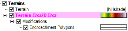
The Cloned terrain model will then have a Terrain Modification created based on the polygon boundaries in the Encroachment Regions layer. The Terrain Modifications will have the elevation of the base water surface along the river's edge plus the Target Water Surface Rise and will fill the floodplain fringe. An example of terrain model before and after modification is shown below.

New Hydraulic Table parameters will be computed for the 2D Flow Areas and the unsteady-flow simulation will be performed.
Filling of the floodplain fringe with the Terrain Modification may block culverts. Blocked culverts (culverts where the terrain minimum is higher that the culvert soffit) will not run in HEC-RAS 6.4 or older. Workarounds include: removing the culvert, adding an additional channel modification, or adjusting the encroachment region. HEC-RAS 6.5 and newer does not have this limitation.
Viewing Floodplain Encroachment Results
Floodplain encroachment results are available along with standard results through RAS Mapper. Encroachment Surcharge and Encroachment Velocity Difference maps are available by default to identify areas that meet (or exceed) the desired water surface rise threshold, as well as unexceptable increases in velocity (i.e. ones that would promote erosion).
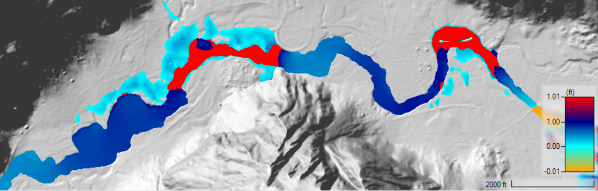
Encroachment Surcharge
The Encroachment Surcharge map is the water surface elevation difference between the Encroached and Base plans. The Surcharge map can be used to quickly identify locations that do not meet the water surface surcharge limits and assist in refining the floodway encroachment. An example Encroachment Surcharge map for a floodway encroachment simulation (one that needs improvement) is shown below.
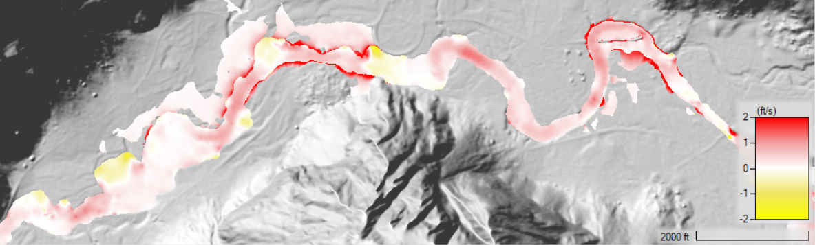
Velocity Difference
This map is the difference in velocities between the Encroached and Base plans. The Velocity map should be used to quickly identify locations that may adversely affect the stability of the river floodplain. An example Velocity Difference map is shown below.
Reference Lines
A traditional profile plot can be generated by creating a Reference Line wherever you would like to evaluate the encroachment results. The Reference Lines are created in the Geometry and must be created prior to simulation. To view results, select the Result and choose the Plot Results Profile context menu from the Plan layer. 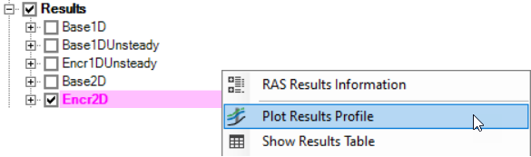
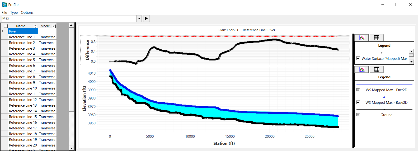
The Plot Results Profile will display the water surface elevation profile for any Reference Lines along with a Difference plot with the Target WS Rise. An example plot for a longitudinal reference line (line running down the center of the river) is shown below.
The plot for a Reference Line that spans the river (a transverse line or cross section) is shown in the figure below, showing the difference in water surface elevations.

Results Tables
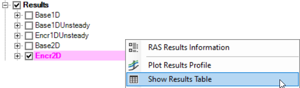
Tables for the encroachment results are available by selecting the Result and choosing the Show Results Table context menu.
Results for the encroachment run will be shown in a table, compared with the base plan. Columns for Stage, Flow, and Velocity are available for both plans as well as the difference between the two simulations. Stage and Velocity values are flow-weighted values and are calculated during the 2D computations.
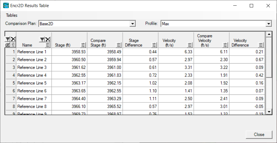
The tables can be user-defined to hide/show columns and to filter reference lines by name.
Downstream Boundary Conditions
The description above does not discuss properly setting the downstream boundary condition. The downstream boundary conditions available in HEC-RAS are Normal Depth, Rating Curve, and Stage Hydrograph. Each of these boundary conditions must be carefully considered for the river hydraulics model. For all boundary conditions, however, you must make sure that the downstream boundary is far enough downstream such that any errors in the boundary condition do not affect the modeling results for the study area.
You must make sure that the downstream boundary is far enough downstream such that any errors in the boundary condition do not affect the modeling results for the study area.
You should also consider the impacts of any floodway encroachment from downstream of the study area.
Specific to modeling floodway encroachment analysis, the downstream boundary condition should consider the impacts of the perspective floodway downstream of the study area. This ensures that downstream impacts are reflected in the upstream model during the analysis. Including the downstream encroachment was a simple affair for 1D steady analysis where a single peak flow was evaluated. For unsteady flow analysis, it is a more complicated situation, because the flow is dynamic resulting in an unknown interaction between the downstream boundary at the time the peak flow passes different portions of the model area.
Normal Depth
The normal depth boundary condition is a simple boundary condition that computes the water surface given a user specified friction slope. This allows for a robust solution through a wide range of flow conditions. However, the normal depth boundary only considers the current geometry and not the impact of conditions from downstream. To use the normal depth option, the user should extend the model downstream far enough that the errors in the produced by the single friction slope do not affect results at the study location. If the downstream boundary is used, not only should the model be extended downstream, but the encroachment polygons should be used to raise the the water surface to meet the Target Rise criteria at the effective downstream boundary of the study reach.
Rating Curve
Using a rating curve for the downstream boundary condition is not trivial. The downstream boundary should include the Target Rise in the water surface, but should only be modified once the water surface reaches the floodway boundary. How to adjust the rating from the intersection elevation to the peak flow can be complicated (a linear transition may or may not be appropriate). Further, the rating curve is a single value rating that will not reflect hysteresis. Therefore, especially in flatter areas, the rating curve will have inherent errors that will not properly represent the stage-flow relationship for a flow hydrograph. If using the rating curve, the Target Rise will most likely be achieved at lower flow (due to the affect of downstream encroachment), further complicating the development of the rating.
Stage Hydrograph
Use of the stage hydrograph is complicated. The new stage, given the new hydrograph response is unknown. Therefore, simply raising the stage by the Target Rise will most likely not be acceptable.