Download PDF
Download page Entering Dam Break Data.
Entering Dam Break Data
Entering dam breach information is accomplished by pressing the button labeled Breach (plan Data). The breach information is stored as part of the current Plan. This was done to facilitate evaluating dam and levee breaching in a real time river forecasting mode. By putting the breach information in the Plan file, the geometric pre-processor does not have to be run again, thus saving computation time during forecasting. The user can also access dam breach information by selecting Dam Breach (Inline Structure) from the Options menu of the Unsteady Flow Analysis window. Once the Breach button is pressed, the Dam Breach window will appear as shown in Figure 14-6.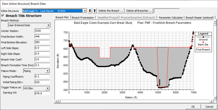
Figure 14 6. Dam Breach Data Editor with Example Dam
As shown in Figure 14-6, the user selects a particular Inline Structure to perform the breach on. At the top left of the editor is an option labeled: Breach This Structure - This check box is used to decide if the program will perform the breach or not. In order for the breach to occur this box must be checked. This box was added to allow the user to turn certain breaches on or off, without losing the user entered breach information.
Inline Structure. This field is used to select the particular inline structure that you want to perform a breach analysis on. The user can enter breach data and perform a breach for more than one dam within the same model.
Delete This Breach. This button is used to clear all of the dam breach information for the currently opened inline structure.
Delete All Breaches. This button is used to delete the dam breach information for all of the inline structures in the model.
Breach This Structure. This check box is used to turn the breaching option on and off without getting rid of the breach data. This box must be checked in order for the software to perform the dam breach. When this box is not checked, no breaching will be performed on this structure.
Next the decision needs to be made as to which "Breaching Method" to use. Currently the user has three Breaching Methodologies to choose from, either User Entered Data, Simplified Physical, or Physical Breaching (DLBreach). The User Entered Data method requires the user to enter all of the breach information (i.e. breach size, breach development time, breach progression, etc…). The Simplified Physical breaching method allows the user to enter velocity versus breach down-cutting and breach widening relationships, which are then used dynamically to figure out the breach progression versus the actual velocity being computed through the breach, on a time step by time step basis. The Physical Breaching (DLBreach) requires material properties for the dam, the core of the dam, and the outer face of the downstream sideslope.
User Enter Breach Data
If the "User Entered Data" Breaching Method is selected, then the following data must be entered for the breaching analysis:
Center Station. This field is used to enter the cross section stationing of the centerline of the breach. The stationing is based on the inline structure that is shown in the graphic.
Final Bottom Width. This field is used to enter the bottom width of the breach when it has reached its maximum size.
Final Bottom Elevation. This field is used to enter the bottom elevation of the breach when it has reached its maximum size.
Left Side Slope. This field is used to enter the left side slope for the trapezoid that will represent the final breach shape. If a zero is entered for both side slopes, the breach will be rectangular. Side slopes are entered in values representing the horizontal to vertical ratio. For example, a value of 2 represents 2 feet horizontally for every 1 foot vertically.
Right Side Slope. This field is used to enter the right side slope for the trapezoid that will represent the final breach shape. If a zero is entered for both side slopes, the breach will be rectangular. Side slopes are entered in values representing the horizontal to vertical ratio. For example, a value of 2 represents 2 feet horizontally for every 1 foot vertically.
Breach Weir Coef. This field is used to enter a weir coefficient that will be used to compute flow through the breach, when the breach is open to the atmosphere. A default value of 2.6 is set automatically, but user's may want to adjust this depending upon the type of dam, and breaching process.
Breach Formation Time (hrs). This field is used to enter the time required for the breach to form. It represents the time from the initiation of the breach, until the breach has reached its full size. The modeler should be very careful in selecting this time. If a linear breach progression rate is selected, then the breach time should be limited to when the breach begins to significantly erode and up to when the major portion of the breach is formed. More information on the breach formation time is provided later in this chapter.
Failure Mode. This selection box contains two options for the failure mode of the breach, a Piping failure or an Overtopping failure. The overtopping failure mode should be selected when the water surface overtops the entire dam and erodes its way back through the embankment, or when flow going over the emergency spillway causes erosion that also works its way back through the embankment. The Piping failure mode should be selected when the dam fails due to seepage through the dam, which causes erosion, which in turn causes more flow to go through the dam, which causes even more erosion. A piping failure will grow slowly at first, but tends to pick up speed as the area of the opening begins to enlarge. At some point during the breach, the embankment above the breach will begin to sluff, at which time a large mass wasting of the embankment will occur.
Piping Coefficient. This field is only used if the Piping failure mode has been selected. The user enters an orifice coefficient into this field. The orifice equation is used to calculate the flow through the breach opening while it is acting in a piping flow manner. Once the embankment above the opening sloughs, and the water is open to the atmosphere, the program transitions to a weir equation for computing the breach flow.
Initial Piping Elev. This field is used to enter the elevation of the center of the piping failure when it first begins to occur.
Trigger Failure At. This field is used to enter the mode in which the breach initiation will be triggered. There are three options available within HEC-RAS for initiating the start of the breach: a water surface elevation (WS Elev), a specific instance in time (Set Time), and a combination of exceeding a water surface elevation for a user specified duration (WS Elev + Duration). With the third option (WS Elev + Duration) the user enters a threshold water surface elevation to start monitoring the location. A duration is also entered. If the water surface remains above the threshold value for the user entered duration, then the breach is initiated. Additionally the user can enter a water surface elevation labeled "Immediate Initiation WS." If the water surface elevation gets up to or beyond this elevation, the breach is immediately initiated.
Starting WS. This field is only used if the user has selected a trigger failure mode of water surface elevation (WS Elev). The user enters a water surface elevation into this field. The water surface represents the elevation at which the breach will begin to occur.
WS Elev+Duration . If the user selects WS Elev+Duration for the trigger mechanism of the failure, then they have three additional fields of data to enter. The first variable is Threshold WS. This variable is the water surface elevation at which the program starts to monitor the flow for duration above this water surface. The second variable is Duration above Threshold. This variable is used to specify the duration that the water surface must be above the threshold water surface elevation before the failure will initiate. The final variable, Immediate initiation WS, is used to instruct the program to begin the breach if the water surface in the structure reaches this elevation or higher, regardless of the duration requirement. This last field is optional.
Set Time. If the user selects the Set Time option, then a starting date and time to initiate the breach must be entered.
Breach Plot.
When this tab is selected, a plot of the inline structure will show up in the graphic window. The plot will show the proposed breach maximum size and location in a red color.
Breach Progression.
When this tab is selected a table will appear in the graphic display window. The table is used to enter a user defined progression curve for the formation of the breach. This is an optional feature. If no curve is entered, the program automatically uses a linear breach progression rate. This means that the dimensions of the breach will grow in a linear manner during the time entered as the full breach formation time. Optionally, the user can enter a curve to represent the breach formation as it will occur during the breach development time. The curve is entered as Time Fraction vs. Breach Fraction. The Time Fraction is the decimal percentage of the full breach formation time. The breach fraction is the decimal percentage of the breach size. Both factors are entered as numbers between zero and one. An example of a user entered nonlinear breach progression rate is shown below. 
User Specified Vertical/Horizontal Growth Rate. When the Breach Progression Tab has been selected, the user can select either the User Specified Vertical/Horizontal Growth Rate (default) or the Proportional Vertical/Horizontal Growth Rate. If the User Specified Vertical/Horizontal Growth Rate option is selected, then the breach will grow in the horizontal direction at a rate that will allow it to reach its full length during the user specified breach time (Figure 14-7.). However, the vertical growth rate, will be based on the user entered Vertical to Horizontal ratio. For the typical case where the breach is wider than it is deep, the breach will reach the final bottom elevation before it has reached the final width. See discussion on Breach Growth Shape, below.
Use Proportional Vertical/Horizontal Growth Rate. When the Breach Progression Tab has been selected, the user can select to use the User Specified Vertical/Horizontal Growth Rate (default) or Proportional Vertical/Horizontal Growth Rate. If Proportional… is selected, then the breach will grow in the horizontal direction based on the formation time. A growth rate will be computed based on the breach width and breach development time, which is then applied to the vertical breach growth rate. See discussion on Breach Growth Shape, below. 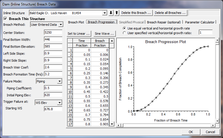
Figure 14 7. Dam Breach Editor with Nonlinear Breach Progression
NOTE: Previous to version 4.2, the horizontal and vertical growth rate of the breach was base on reaching the maximum breach depth and width at the user entered "Breach Formation Time". This means if a user put in breach dimensions of 400 ft wide and 100 ft deep, over a period of 2 hours, the horizontal growth rate was 200ft/hr and the vertical growth rate was 50 ft/hr. While this was generally ok for Dam breaches, it was not ok for levee breaching, in that levee breaches are much wider than they are tall. As of version 4.2, RAS computes the breach growth rate based on the breach "Final Bottom Width" and the user entered "Breach Formation Time". Then this same breach growth rate is used for the vertical down cutting of the breach. So in the previous example of a 400 ft breach bottom width and a 2 hour breach development time, the growth rate is 200 ft/hr, which is used for both the down cutting and widening rates. User's can change the vertical Breach Growth Rate by entering a value other than 1.0 under the option labeled "User Specified Vertical/Horizontal Growth Ratio" and the Breach Progression Tab. If a user enters a value of 0.5, that means you want the vertical growth rate to be half of what the Horizontal growth rate gets computed to be.
WARNING: The breach growth rate change described in the previous paragraph will generally results in RAS version 4.2 and newer yielding a higher peak flow through the breach, than versions 4.1 and older. If the user wants the same results as version 4.1 and older, you must compute a vertical/horizontal growth rate that will results in the breach reaching its maximum width and depth at the end of the breach formation time. For example (assuming an overtopping breach), if you specified a 400 ft breach bottom width and a 2 hour breach formation time, this is a horizontal growth rate of 200 ft/ hour. However, if you Dam is only 100 ft high, then to reproduce the version 4.1 or older results, the user would need to enter a "User Specified Vertical/Horizontal Growth Ratio" of 0.25. This would cause the program to grow the breach vertically down to the 100 ft depth in exactly 2 hours. Piping breaches are more complicated, in that they have an initial elevation for the hole, and the vertical growth is both up and down.
Breach Repair (Optional). This option allows the user to have the breach fill back in during a simulation. This would most often be used for levee breaches, but could also be used for a dam breach if the user were running a long term simulation or if it was assumed that some effort would be put in place to fill a breach back in during a failure. When the Breach Repair tab is selected, the editor will appear as shown in Figure 14-8.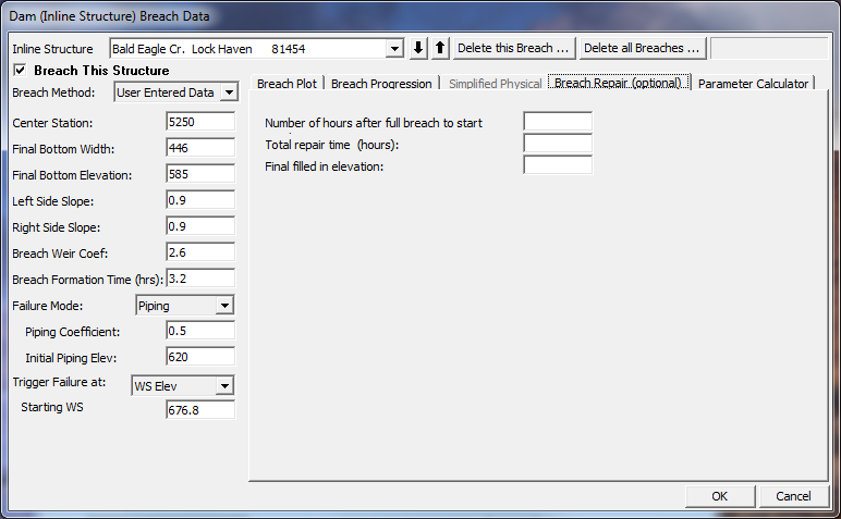
Figure 14 8. Dam Break Editor with Breach Repair Tab Active.
The Breach Repair Option requires the user to enter three pieces of information:
Number of hours after full breach to start repair: This field is used to enter the amount of time (in hours) it takes to start the repair process after the breach has occurred.
Total repair time (hours): This field is used to enter the total amount of time that it will take to perform the breach repair, in hours.
Final filled in elevation: This field is used to enter the top elevation of the final repaired breach.
Simplified Physical Breaching
If the User selects to use the "Simplified Physical" Breach Method from the drop down at the top of the editor, the Breaching Editor will change to look the following way: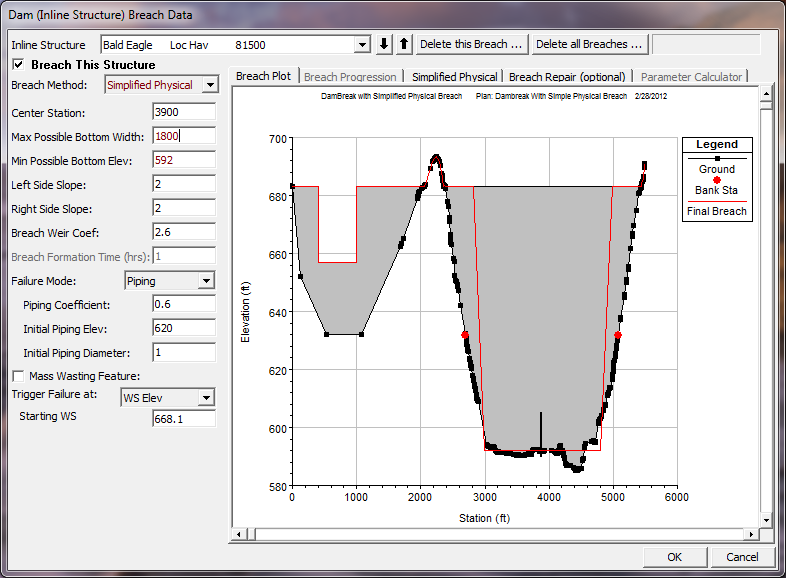
Figure 14 9. Simplified Physical Breaching Option for HEC-RAS
Once the User selects "Simplified Physical" breaching option, there are several fields in which labels change, some additional information required, and some previous information that is not required. The main changes between this method and the "User Entered Data" breach method, are the following:
Max Possible Bottom Width – This field is now used to enter a maximum possible breach bottom width. This does not mean this will be the final breach bottom width, it is really being used to limit the breach bottom width growth to this amount. The actual bottom width will be dependent on the velocity verses erosion rate data entered, and the hydraulics of flow through the breach. This field is used to prevent breaches from growing larger than this user set upper limit during the run.
Min Possible Bottom Elev – This field is used to put a limit on how far down the breach can erode during the breaching process. This is not necessarily the final breach bottom elevation, it is a user entered limiter (I.e. the breach cannot go below this elevation). The final breach elevation will be dependent on the velocity verses erosion rate data entered, and the hydraulics of flow through the breach.
Starting Notch Width or Initial Piping Diameter – If the Overtopping failure mode is selected, the user will be asked to enter a starting notch width. The purpose of this is that the software will us this width at the top of the dam to compute a velocity, from the velocity it will get a down cutting erosion rate (based on user entered data), which will be used to start the erosion process. If a Piping Failure model is selected, the user must enter an initial piping diameter. Once the breach is triggered to start, this initial hole will show up immediately. A velocity will be computed through it, then the down cutting and widening process will begin based in user entered erosion rate data.
Mass Wasting Feature – This option allows the user to put a hole in the Dam or the Levee at the beginning of the breach, in a very short amount of time. This option would probably most often be used in a levee evaluation, in which a section of the levee may give way (Mass Wasting), then that initial hole would continue to erode and widen based on the erosion process. The required data for this option is a width for the mass wasting hole; duration in hours that this mass wasting occurs over (this would normally be a short amount of time); and the final bottom elevation of the initial mass wasting hole (it is assumed that the hole is open all the way to the top of the levee or Dam if this option is used).
Velocity vs. Downcutting and Widening Erosion Rates. When using the "Simplified Physical" breaching option, the user is required to enter velocity versus Downcutting erosion rates, as well as velocity versus erosion widening rates. To enter this data the user selects the "Simplified Physical" breach Tab. When this Tab is selected the editor will look like the following:
Figure 14 10. HEC-RAS Simplified Physical Breach Option.
As shown in Figure 14-10 above, the user is required to enter Velocity versus Down-cutting erosion rates and velocity versus erosion widening rates. This data is often very difficult to come by. User's will need to consult with Geotechnical engineers to come up with reasonable estimates of this data for your specific Levee or Dam. Another way to estimate this information is to try to derive it by simulating a historic Levee or Dam breach, and adjusting the velocity versus erosion rate data until the model simulates the correct breach width and time. This is obviously an iterative process, and may require the user to perform this at multiple locations to see if there is a consistent set or erosion rates that will provide a reasonable model for simulating Levee breaches (or Dams) in your geographical area.
We realize that this data is not readily available for any specific levee or dam. The hope is that over time we will be able to develop guidelines for these erosion rates based on analyzing historical levee and dam breaches.
Once all of the Dam Breach data are entered, press the OK button to have the data accepted. However, the data is not saved to the hard disk at this point. You must save the currently opened plan in order for the breach information to be save to the hard disk.