Download PDF
Download page Entering and Editing Bridge Data.
Entering and Editing Bridge Data
![]()
To enter bridge data the user presses the Bridge/Culvert button on the geometric data window (Figure 5-1). Once the bridge/culvert button is pressed, the Bridge/Culvert Data Editor will appear as shown in Figure 5-12 (your bridge/culvert editor will come up with a blank window until you have entered the bridge data). To add a bridge to the model, do the following:
- Select the river and reach that you would like to place the bridge in. Selecting a reach is accomplished by pressing the down arrow on the river and reach box, then selecting the river and reach of choice.
- Go to the Options menu and select Add a Bridge and/or Culvert from the list. An input box will appear prompting you to enter a river station identifier for the new bridge.
- Enter all of the required data for the new bridge. This includes:
- Bridge Deck
- Sloping Abutments (optional)
- Piers (optional)
- Bridge modeling approach information
- Enter any desired optional information. Optional bridge information is found under the Options menu at the top of the window.
- Press the Apply Data button for the interface to accept the data.
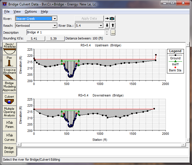
Figure 5 12 Bridge/Culvert Data Editor
The required information for a bridge consists of: the river, reach, and river station identifiers; a short description of the bridge; the bridge deck; bridge abutments (if they exist); bridge piers (if the bridge has piers); and specifying the bridge modeling approach. A description of this information follows:
River, Reach and River Station. The River and Reach boxes allow the user to select a river and reach from the available reaches that are defined in the schematic diagram. The reach label defines which reach the bridge will be located in. The River Station tag defines where the bridge will be located within the specified reach. The river station tag does not have to be the actual river station of the bridge, but it must be a numeric value. The river station tag for the bridge should be numerically between the two cross sections that bound the bridge. Once the user selects Add a Bridge and/or Culvert from the options menu, an input box will appear prompting you to enter a river station tag for the new bridge. After the river station tag is entered, the two cross sections that bound the bridge will be displayed on the editor.
Description. The description box is used to describe the bridge location in more detail than just the reach and river station. This box has a limit of 256 characters. Only the first line of information is displayed, unless the button to the right of the box is pressed. Also, the first 40 characters of the description are used as a label for bridge plots and tables.
Bridge Deck/Roadway. The bridge deck editor is used to describe the area that will be blocked out due to the bridge deck, road embankment and vertical abutments. To enter bridge deck information the user presses the Deck button on the Bridge/Culvert Data Editor. Once the deck button is pressed, the Deck Editor will appear as in Figure 5-13 (except yours will be blank). The information entered in the deck editor consists of the following: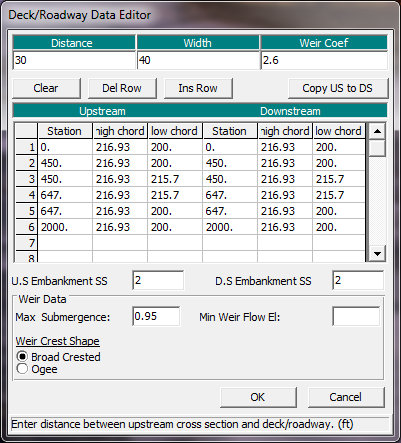
Figure 5 13 Bridge Deck/Roadway Data Editor
Distance - The distance field is used to enter the distance between the upstream side of the bridge deck and the cross section immediately upstream of the bridge (see Figure 5 14, "Upstream Distance"). This distance is entered in feet (or meters for metric).
Width - The width field is used to enter the width of the bridge deck along the stream (Figure 5 14, "Bridge Width"). The distance between the bridge deck and the downstream bounding cross section will equal the main channel reach length minus the sum of the bridge "width" and the "distance" between the bridge and the upstream section. The width of the bridge deck should be entered in feet (meters for metric). 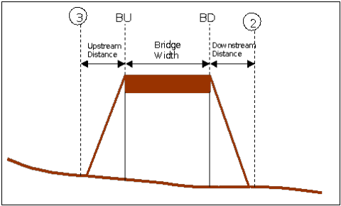
Figure 5 14 Bridge Profile with Upstream Distance, Bridge Width, and Downstream Distance
Weir Coefficient - Coefficient that will be used for weir flow over the bridge deck in the standard weir equation.
Upstream Stationing, High Chord, and Low Chord - This table is used to define the geometry of the bridge deck on the upstream side of the bridge. The information is entered from left to right in cross section stationing. The deck is the area between the high and low chord elevation information. The stationing of the deck does not have to equal the stations in the bounding cross section, but it must be based on the same origin. The Del Row and Ins Row buttons allow the user to delete and insert rows.
Downstream Stationing, High Chord, and Low Chord - This portion of the table is used to define the geometry of the bridge deck on the downstream side of the bridge. If the geometry of the downstream side is the same as the upstream side, then the user only needs to press the Copy US to DS button. When this button is pressed, all of the upstream bridge deck information is copied to the downstream side. If the bridge deck information on the downstream side is different than the upstream side, then the user must enter the information into the table.
U.S. Embankment SS - This field is used to enter the slope of the road embankment on the upstream side of the bridge. The slope should be entered as the horizontal to vertical distance ratio of the embankment. This variable is generally not used in the computations, but is used for display purposes in the profile plot. However, if the user has selected the FHWA WSPRO Bridge method for low flow, this field will be used in the computation of the bridge discharge coefficient.
D.S. Embankment SS - This field is used to enter the slope of the road embankment on the downstream side of the bridge. The slope should be entered as the horizontal to vertical distance ratio of the embankment. This variable is generally not used in the computations, but is used for display purposes in the profile plot. However, if the user has selected the FHWA WSPRO Bridge method for low flow, this field will be used in the computation of the bridge discharge coefficient.
Max Submergence - The maximum allowable submergence ratio that can occur during weir flow calculations over the bridge deck. If this ratio is exceeded, the program automatically switches to energy based calculations rather than pressure and weir flow. The default value is 0.98 (98 percent submerged).
Submergence Criteria - When submergence occurs there are two choices available to figure out how much the weir coefficient should be reduced due to the submergence. The first method is based on work that was done on a trapezoidal shaped broad crested weir (FHWA, 1978). The second criterion was developed for an Ogee spillway shape (COE,1965). The user should pick the criterion that best matches their problem.
Min Weir Flow El - This field is used to set the minimum elevation for which weir flow will begin to be evaluated. Once the computed upstream energy becomes higher than this elevation, the program begins to calculate weir flow. However, the weir flow calculations are still based on the actual geometry of the deck/roadway, and are not affected by this elevation. If this field is left blank, the elevation that triggers weir flow is based on the lowest high chord elevation on the upstream side of the bridge deck. Also, weir flow is based on the elevation of the energy grade line and not the water surface.
Once all of the bridge deck information is entered, the user should press the OK button at the bottom of the window. Pressing the OK button tells the interface to accept the data and close the window. Once the deck editor closes, the graphic of the bridge deck will appear on the Bridge/Culvert Data window. An example of this is shown in Figure 5-15. Note! The data are not saved to the hard disk at this point. Geometric data can only be saved to the hard disk from the File menu of the Geometric Data window. 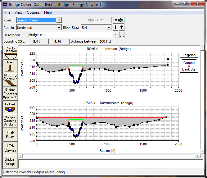
Figure 5 15 Example Bridge Deck Plotted on Bounding Cross Sections
Sloping Bridge Abutments. The sloping bridge abutments editor is used to supplement the bridge deck information. Whenever bridge abutments are protruding towards the main channel (sloping inward abutments), it will be necessary to block out additional area that cannot be accounted for in the bridge deck/roadway editor. If the bridge has vertical wall abutments, then it is not necessary to use this editor. Vertical wall abutments can be included as part of the bridge deck/roadway data. To add sloping abutments, the user presses the
Sloping Abutment button on the Bridge/Culvert Data editor. Once this button is pressed the Abutment data editor will appear as in Figure 5-16.
Sloping abutments are entered in a similar manner to the bridge deck/roadway. When the editor is open, it has already established an abutment # of 1. Generally a left and right abutment is entered for each bridge opening. Sloping abutment data are entered from left to right, looking in the downstream direction. In general it is usually only necessary to enter two points to describe each abutment.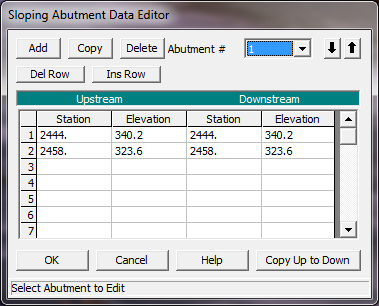
Figure 5 16 Abutment Data Editor
The data for each abutment consist of a skew angle (this is optional) and the station and elevation information. The station and elevation information represents the high chord information of the abutment. The low chord information of the abutment is assumed to be below the ground, and it is therefore not necessary to enter it. The geometric information for each abutment can vary from upstream to downstream. If this information is the same, then the user only needs to enter the upstream geometry and then press the Copy Up to Down button.
To add additional sloping abutments, the user can either press the ADD or the Copy button. To delete an abutment, press the Delete button. Once all of the abutment data are entered, the user should press the OK button. When the OK button is pressed, the abutment information is accepted and the editor is closed. The abutments are then added to the bridge graphic on the Bridge/Culvert Data editor. An example of a sloping bridge abutment is shown in Figure 5-17. This graphic is zoomed in on the left abutment of the bridge.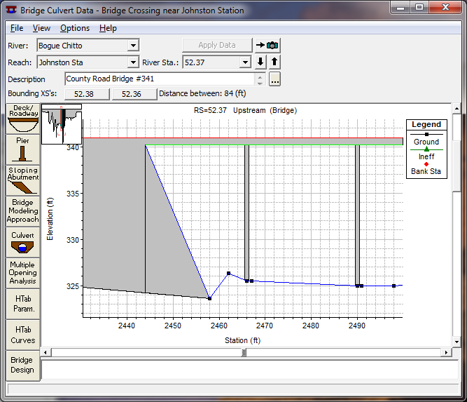
Figure 5 17 Example of a Sloping Abutment
Bridge Piers. The bridge pier editor is used to describe any piers that exist in the bridge opening. Note! All piers must be entered through the Pier Editor, they should not be included as part of the ground or bridge deck. Several of the low flow bridge computations require that the piers be defined separately in order to determine that amount of area under the water surface that is blocked by the piers. If the piers are included with the ground or the bridge deck, several of the methods will not compute the correct amount of energy loss for the piers.
To enter pier information, the user presses the Pier button on the Bridge/Culvert Data editor. Once the pier button is pressed, the pier data editor will appear as in Figure 5-18 (Except yours will not have any data in it yet).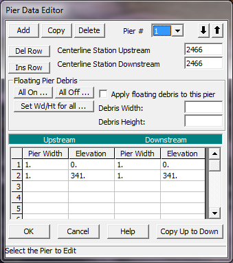
Figure 5 18 Pier Data Editor
When the pier data editor appears it will have already defined the first pier as pier # 1. The user is required to enter a centerline station for both the upstream and downstream side of the pier. The pier geometry is entered as pier widths and elevations. The elevations must start at the lowest value and go to the highest value. Generally the elevations should start below the ground level. Any pier area below the ground will be clipped off automatically. Pier widths that change at a single elevation are handled by entering two different widths at the same elevation. The order of the widths in the table is very important. Keep in mind that the pier is defined from the ground up to the deck. If the pier geometry on the downstream side is the same as the upstream side, simply press the Copy Up to Down button after the upstream side data are entered.
The user also has the option of defining floating pier debris. If the Floating Debris option is selected, the user will need to enter a width and a height for the debris. The user can set a different height and width of debris for each pier, or there is a button that will allow the user to enter a single height and width that will be used for all of the piers (Set Wd/Ht for all…). Additionally there are buttons to turn pier debris on or off for all of the piers of the bridge (All On… and All Off...).
Additional piers can be added by pressing either the Add or the Copy button. If the piers are the same shape, it is easier to use the copy button and simply change the centerline stations of the new pier. To delete a pier, simply press the Delete button and the currently displayed pier will be deleted. Once all of the pier data are entered, press the OK button. When the OK button is pressed, the data will be accepted and the pier editor will be closed. The graphic of the bridge will then be updated to include the piers. An example bridge with piers is shown in Figure 5-19. This graphic is only the upstream side of the bridge with a zoomed in view.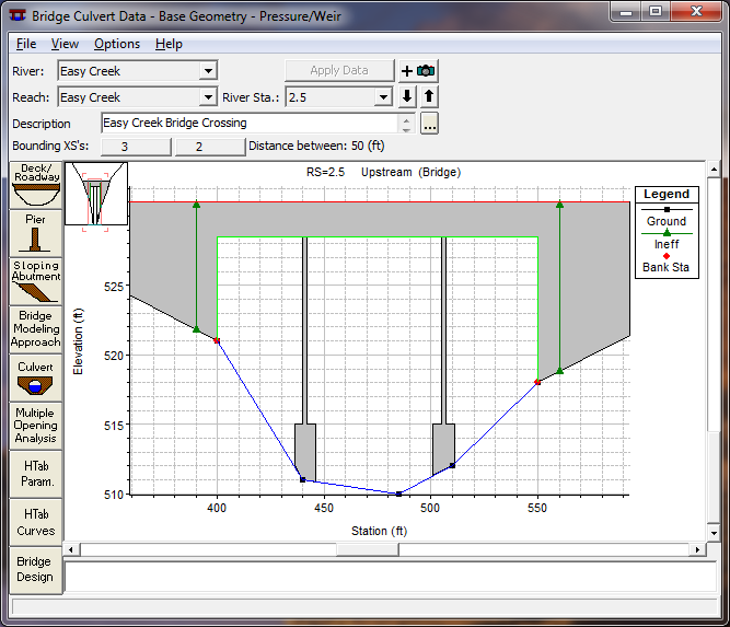
Figure 5 19 Bridge with Piers, zoomed in view
Bridge Modeling Approach. The Bridge Modeling Approach editor is used to define how the bridge will be modeled and to enter any coefficients that are necessary. To bring up the Bridge Modeling Approach editor press the Bridge Modeling Approach button on the Bridge/Culvert Data editor. Once this button is pressed, the editor will appear as shown in Figure 5-20 (Except yours will only have the default methods selected).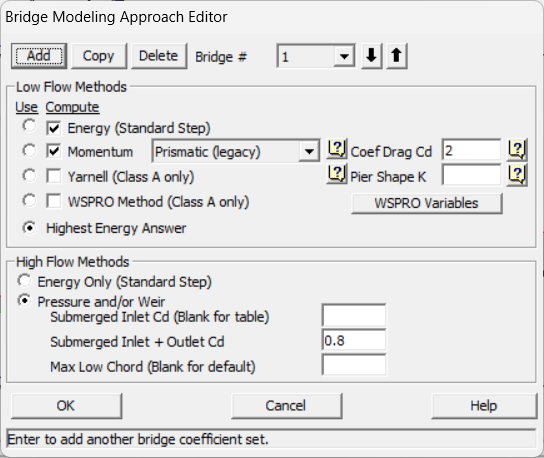
Figure 5 20 Bridge Modeling Approach Editor
When the Bridge Modeling Approach editor comes up it will be ready to enter data for the first bridge opening (coefficient set # 1). If there is more than one bridge opening at the current location, the user can either use a single set of modeling approaches and coefficients, or establish a different set for each bridge opening.
Establishing a bridge modeling approach consists of defining which methods the program will use for low flow computations and high flow (flow at or above the maximum low chord) computations. The user can instruct the program to use any or all of the low flow methods during the computations by clicking the buttons under the Compute column. If either the Momentum or Yarnell method are selected, the user must enter a value for the pier loss coefficient that corresponds to that method. If the WSPRO method is selected, the user must press the "WSPRO Variables" button and enter additional information that is required for the method. Once the WSPRO Variables button is pressed, a data editor as shown in Figure 5-21 will appear.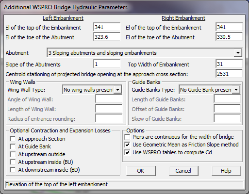
Figure 5 21 WSPRO Data Editor
As shown in Figure 5-21, there are several variables that must be entered as well as some options that are available to the user. All of the required variables shown on the WSPRO data editor are used in the computation of the discharge coefficient, C, which is used in the WSPRO expansion loss equation. A detailed discussion of how the discharge coefficient is computed can be found in appendix D of the HEC-RAS Hydraulic Reference manual. The following is a description of each of the variables on the WSPRO Data Editor:
El of the top of the Embankment - These fields are used for entering the elevation of the top of the embankment (top of road) at the edges of the bridge opening. An elevation must be entered for both the left and right side of the bridge opening.
El of the toe of the Abutment - These fields are used for entering the elevation of the abutment toe (elevation at the station in which the abutment toe intersects with the natural ground inside the bridge opening) on both the left and right side of the bridge opening.
Abutment Type - This field is used for selecting the type of abutments. There are four abutment types available from this selection box.
Slope of the Abutments - This field is used for entering the slope of the abutments. This slope is taken as the horizontal distance divided by the vertical distance. If the abutments are vertical walls, then this field should be left blank or set to zero. If the left and right abutments do not have the same slope, take an average of the two and enter that into this field.
Top Width of Embankment - This field is used for entering the width of the top of the road embankment, in the area of the bridge opening. If the topwidth of the embankment varies from one end of the bridge opening to the other, use an average of the two widths.
Centroid stationing of the projected bridge opening at the approach cross section - For the WSPRO bridge method, it is necessary to calculate the water surface topwidth inside of the bridge opening, and then project that width onto the approach cross section. The program calculates the conveyance within this projected width at the approach cross section. This conveyance is used in calculating a channel contraction ratio, which is an integral part in the calculation of the discharge coefficient. If this field is left blank, the program will automatically center the computed topwidth, such that the center of the topwidth will be at the center of conveyance at the approach cross-section. The user can override this by entering their own centroid stationing value for the approach cross section.
Wing Walls - This field is used for selecting the type of wing walls. There are three choices available in the selection box: No wing walls present; Angular wing walls; and Rounded wing walls. If the user selects "Angular wing walls", then the fields labeled "Angle of Wing Wall" and "Length of Wing Wall" become active and must be filled out. If the user selects "Rounded wing walls", then the fields "Length of wing walls" and "Radius of entrance rounding" become active and must be filled out. If the user selects "No wing walls present" then no other information on wing walls is necessary. For more information on wing walls see appendix D of the HEC-RAS Hydraulic Reference manual.
Guide Banks Type - This field is used for selecting the type of guide banks if any exist. There are three choices available from the selection box: No guide bank present; Straight; and Elliptical. If the user selects "Straight" then the fields labeled "Length of guide banks", "Offset of Guide Banks", and "Skew of Guide Banks" become active and must be filled out. If the use selects "Elliptical" then only the fields "Length of Guide Banks" and "Offset of Guide Banks" become active. If the user selects "No Guide Bank present" then no other information about guide banks is necessary. For more information on Guide Banks see appendix D of the HEC-RAS Hydraulic Reference manual.
Optional Contraction and Expansion Losses - This box allows the user to turn on contraction and expansion losses at locations that are traditionally not in the WSPRO methodology. The basic WSPRO bridge method only computes expansion losses in the expansion reach (between the exit cross section and the section just downstream of the bridge). This option allows the user to turn on contraction and expansion losses individually at the following locations: downstream inside of the bridge; upstream inside of the bridge; upstream outside of the bridge; at the end of a guide bank (if guide banks exist); and at the approach cross section. The default for the WSPRO method is that contraction and expansion losses will not be calculated at these locations. Users should not turn these options on unless they feel that the standard WSPRO bridge approach is not producing enough energy loss through the bridge.
Three other options that the user has control over are: specifying that the piers are continuous the whole way through the bridge or not; using the Geometric Mean friction slope averaging technique through the bridge computations (from exit to approach section); and using the WSPRO tables to compute the Cd coefficient, rather than the theoretical equation. The default for the WSPRO methodology is to assume that the piers are continuous through the bridge, to use the Geometric Mean friction slope method, and compute Cd with the theoretical equation.
After all of the variables have been entered, the user must press the OK button for the WSPRO variables to be accepted. For more information about the computation of the discharge coefficient, and these data variable, see appendix D of the HEC-RAS Hydraulic Reference manual.
Once the user has selected which low flow bridge methods will be computed, they must also specify which of those methods will be used as the final answer to continue the computations on upstream with. Only one of the methods can be selected as the answer to "Use" in order to continue the computations upstream. An alternative to selecting a single method to use is to instruct the program to use the answer with the highest computed upstream energy elevation. This is accomplished by pressing the button under the "Use" column that corresponds to the Highest Energy Answer text field.
For a High Flow Method, the modeler can choose between Energy based calculations or pressure and weir flow calculations. If pressure and weir flow is the selected high flow method, the user must enter coefficients for the pressure flow equations. The first coefficient applies to the equation that is used when only the upstream side (inlet) of the bridge is submerged. If this coefficient is left blank, the program selects a coefficient based on the amount of submergence. If the user enters a coefficient, then that value is used for all degrees of submergence. The second coefficient applies to the equation that is used when both the upstream and downstream end of the bridge is sub-merged. Generally this coefficient is around 0.8. For more information on pressure flow coefficients see Hydraulics of Bridge Waterways (FHWA, 1978).
Max Low Chord - This field is used to set the maximum elevation of the deck low chord, and therefore the elevation at which pressure flow begins to be calculated. If this field is left blank, then the elevation that triggers pressure flow calculations is based on the highest low chord elevation on the upstream side of the bridge deck. If the user enters a value in this field, then the value set will be used to trigger when pressure flow calculations begin. Pressure flow is triggered when the energy elevation exceeds the maximum low chord. When pressure flow is calculated, the answer is compared to the low flow answer and the higher of the two is selected. Alternatively, the user can tell the program to use the water surface instead of the energy elevation to trigger pressure flow calculations. This option can be found under the Bridge and Culvert Options section of this manual.
Once all of the bridge modeling approach information is entered, the user should press the OK button. When the OK button is pressed the information will be accepted and the editor will close. Remember! The data are not saved to disk at this point, it is only accepted as being valid. To save the geometric data, use the File menu from the Geometric Data Editor window.