Download PDF
Download page Entering and Editing Culvert Data.
Entering and Editing Culvert Data
Culvert data are entered in the same manner as bridge data. To enter culvert data the user presses the Bridge/Culvert button on the Geometric Data window (Figure 5-1). Once this button is pressed, the Bridge/Culvert Data Editor will appear (Figure 5-12). To add a culvert group to the model the user must then do the following:
- Select the river and reach that you would like to place the culvert in. This selection is accomplished by pressing the down arrow on the river and reach boxes and then selecting the river and reach of choice.
- Go to the Options menu of the Bridge/Culvert editor and select Add a Bridge and/or Culvert from the list. An input box will appear prompting you to enter a river station identifier for the new culvert group. After entering the river station, press the OK button and the cross sections that bound the new culvert group will appear in the editor.
- Enter all of the required data for the culvert group. This includes the road embankment information and the culvert specific data. The roadway information is entered in the same manner as a bridge (using the deck/roadway editor). To enter culvert specific data, press the Culvert button on the Bridge/Culvert Data editor.
- Once all of the culvert data are entered, press the OK button in order for the interface to accept the information.
River, Reach and River Station. The River and Reach boxes allow the user to select a river and reach from the available reaches that were put together in the schematic diagram. The reach label defines which reach the culvert will be located in. The River Station tag defines where the culvert will be located within the specified reach. The River Station tag does not have to be the actual river station of the culvert, but it must be a numeric value. The River Station tag for the culvert should be numerically between the two cross sections that bound the culvert. Once the user selects Add a Bridge and/or Culvert from the options menu, an input box will appear prompting you to enter a River Station tag for the new culvert. After the River Station tag is entered, the two cross sections that bound the culvert will be displayed on the editor.
Description. The description box is used to describe the culvert location in more detail than just the river, reach and river station. This box has a limit of 256 characters. Only the first line of information is displayed, unless the button to the right of the box is pressed. Also, the first 40 characters of the description are used as a label for culvert plots and tables.
Culvert Road Embankment. The culvert road embankment is virtually the same as the bridge deck/roadway information. The road embankment is used to describe the area blocking the stream and the roadway profile. The only difference in the information for culverts is that the low chord elevations should be left blank or set to elevations below the ground data. This will cause the road embankment to completely fill the channel up to the roadway elevations (high chord data). Therefore, the only opening below the roadway will be whatever culvert openings are entered.
To enter the culvert roadway information, press the Deck/Roadway button on the Bridge/Culvert Data Editor window. For an explanation of the deck information, please review the section entitled Bridge Deck/Roadway found earlier in this chapter.
Culvert Data. To enter culvert specific information, press the Culvert button on the Bridge/Culvert Data Editor window. When this button is pressed, the Culvert Data Editor will appear as shown in Figure 5-23 (Except yours will be blank). The information entered in the Culvert Data Editor consists of the following: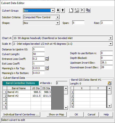
Figure 5 23 Culvert Data Editor
Culvert Group - The culvert group is automatically assigned to "Culvert #1" the first time you open the editor. The user can enter up to ten culvert types if they are working on a multiple culvert/opening problem. If all of the culvert barrels are exactly the same, then only one culvert group should be entered. The number of barrels is an input parameter in the culvert data. If the user has culverts that are different in shape, size, elevation, or loss coefficients, then additional culvert groups must be added for each culvert type. To add an additional culvert group you can either use the Add or Copy buttons. The Add button increments the culvert group and clears the culvert editor. The Copy button increments the culvert group and makes a copy of the original culvert data. Once a copy is made of a culvert, the user can change any of the existing culvert information. Culverts can be deleted by pressing the Delete button.
Solution Criteria - This option allows the user to select between taking the higher of the inlet control and outlet control answers (Computed Flow Control), or specifically selecting the Inlet control or Outlet control answer. The default is to let the program compute both and take the higher of the two. In general this should be left this way. The only time a user should specifically select Inlet control or Outlet control, is when they feel the program is in error by selecting the higher of the two answers.
Rename - This button allows the user to put in their own identifier for each of the culvert types. By default the culvert types will be labeled "Culvert #1," "Culvert #2," and so on. The user can enter up to twelve characters for each culvert type.
Shape - The shape selection box allows the user to select from one of the nine available shapes. This selection is accomplished by pressing the down arrow on the side of the box, then selecting one of the nine available shapes.
Span - The span field is used to define the maximum width inside of the culvert. The span is left blank for circular culverts.
Rise - The rise field describes the maximum height inside of the culvert.
Chart # - This field is used to select the Federal Highway Administration Chart number that corresponds to the type and shape of culvert being modeled. Once the user has selected a culvert shape, the corresponding FHWA chart numbers will show up in the chart # selection box. More information on FHWA chart numbers can be found in the Hydraulics Reference manual.
Scale# - This field is used to select the Federal Highway Administration Scale number that corresponds to the type of culvert entrance. Once the user has selected a culvert shape and chart #, the corresponding FHWA scale numbers will show up in the scale selection box. More information on FHWA scale numbers can be found in the Hydraulics Reference manual.
Distance to Upstream XS - This field is used to locate the culvert in space, relative to the two cross sections that bound the culvert crossing. The user should enter the distance between the upstream cross section and the upstream end of the culvert barrel.
Culvert Length - The culvert length field describes the length of the culvert along the centerline of the barrel.
Entrance Loss Coefficient - The coefficient entered in this field will be multiplied by the velocity head inside of the culvert at the upstream end. This value represents the amount of energy loss that occurs as flow transitions from the upstream cross section to inside the culvert barrel. This coefficient is used in the outlet control computations, and will not affect inlet control computations, as they are performed with the Federal Highway Inlet Control equations directly.
Exit Loss Coefficient - The coefficient entered in this field will be multiplied by the change in velocity head from inside the culvert to outside the culvert at the downstream end. This value represents the energy loss that occurs as water exits the culvert. This coefficient is used in the outlet control computations.
Manning's n for Top - The n-value fields are used for entering the Manning's n values of the culvert barrel. This version of HEC-RAS allows the user to enter a separate n value for the top (which includes top and sides) of the culvert, as well as for the bottom. If the culvert has the same roughness for the top and bottom, the user can enter the value for the top. The Manning's n value for the bottom will automatically be copied from the top field.
Manning's n for Bottom – This field is used to enter a Manning's n value for the bottom of the culvert. This n value will be used up to a user specified depth inside of the culvert. When the water surface gets higher than that depth, a composite Manning's n value is computed based on the bottom and top n values and their corresponding wetted perimeters.
Depth to use Bottom n – This field is used to specify the depth that the "Bottom n value" is applied inside of the culvert. The surface of the culvert below this depth is given the n value for the bottom of the culvert, while the surface of the culvert above this depth is given the n value for the top of the culvert.
Depth Blocked – This field is used to block off a portion of the bottom of the culvert. When a value is entered into this field, the culvert is completely blocked up to the depth specified. This blocked out area persists the whole way through the culvert.
Upstream Invert Elevation - This field is used to describe the elevation of the culvert invert at the upstream end.
Downstream Invert Elevation - This field is used to describe the elevation of the culvert invert at the downstream end.
# Barrels - This field is used to display the number of identical barrels. The number of identical barrels is limited to 25. To enter more than one identical barrel, the user must provide different centerline stationing information for each barrel. As the centerline stationing information is added, the number of identical barrels will automatically change to reflect the number of centerline stations. The user does not enter anything into this field, it is just used to display the number of identical barrels.
Barrel Centerline Stations - This table is used to enter the stationing of each culvert barrel. Centerline stations must be provided for both the upstream and downstream side of each culvert barrel.
Barrel GIS Data – This table is used to enter X, Y coordinates for a line representing each barrel. X, Y coordinates are only used when culverts are connected to 2D Flow Areas. When a Culvert is put into a Bridge/Culvert crossing of a 1D River Reach, then the X, Y coordinates are not needed or used. This table is only relevant to Lateral Structures and SA/2D Area Connections in which culverts will be connected to 2D Flow Area cells. It is not needed for pure 1D bridge/Culvert crossings.
Once all of the culvert information is entered, the user should press the OK button at the bottom of the window. Pressing the OK button tells the interface to accept the data and close the window. Once the culvert editor is closed, the graphic of the culvert will appear on the Bridge/Culvert Data editor window. An example culvert with two culvert types and two identical barrels for each culvert type is shown in Figure 5-24. Note! The data are not saved to the hard disk at this point. Geometric data can only be saved from the File menu on the Geometric Data window.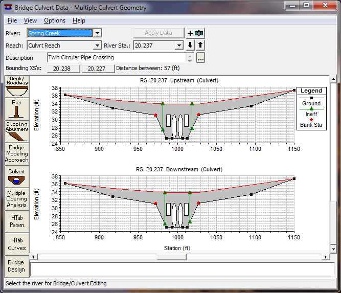
Figure 5 24 Bridge/Culvert Data Editor with example culvert