Download PDF
Download page Geometric Data Options.
Geometric Data Options
A few new options have been added to the HEC-RAS Geometric Data editor. To select one of the options go to the Options menu at the top of the Geometric Data Editor, and select the desired option. The following is a list of the currently available options:
Main Channel Manning's n Value Compositing
When this option is selected, the window shown in the figure below will be invoked.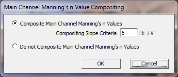
Main Channel Manning's n Value Compositing Editor
This editor allows the user to control how HEC-RAS will composite Manning's n values for the main channel only. The default option is the top option. This option will composite all of the main channel manning's n values into a single n value, as long as the side slopes of the main channel are greater than 5H:1V. The user has the option to change this slope criterion. The second option is to tell HEC-RAS to not composite Manning's n values for any of the cross sections in the model. For more details on Manning's n value compositing for the main channel, see the Hydraulic reference manual.
Hydrologic Unsteady Routing
This option allows the user to define portions of a model to be routed with a hydrologic routing technique instead of using the full unsteady flow equations. The software will simultaneously solve the unsteady flow equations and the hydrologic routing reaches each time step. This option is very useful when encountering portions of the model that are very steep and full unsteady flow routing is either unstable or not possible at all. Currently the only hydrologic routing method available is Modified Puls routing. This option only works as part of an unsteady flow model, and is ignored when using a geometry file in steady flow mode.
To use the hydrologic routing option, go to the Options menu at the top of the Geometric Editor and select the option called Hydrologic Unsteady Routing. When this option is selected the following window will appear.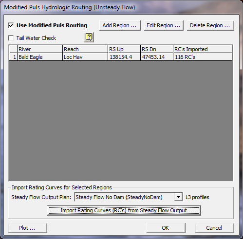
Hydrologic Unsteady Flow Routing Editor
To use the Modified Puls routing option, the user must first create a steady flow plan with the exact same geometry file. The purpose of the steady flow plan is to compute a range of water surface profiles from very low to the highest expected flow rate. The results from the steady flow run are used within the hydrologic routing reaches in order to provide the necessary discharge-volume relationships required by Modified Puls routing. As shown in the figure above, a Steady Flow Output Plan must be selected at the bottom of the editor, which will be used for importing the computed rating curves. Based on the computed rating curves from the steady flow run, and the known distances between cross sections, the program can compute a volume for any flow rate on the fly, in order to solve the Modified Puls equations.
Users can establish hydrologic routing reaches almost anywhere in the model. A hydrologic routing reach must be at least two cross sections long. A hydrologic routing reach can be an upstream piece, downstream piece, or an intermediate piece of any existing HEC-RAS unsteady flow river reach. A hydrologic routing reach can also encompass an entire HEC-RAS river reach. Hydrologic routing reaches can contain bridges/culverts and lateral structures, but it cannot contain an inline structure. If you have an inline structure within a reach that you want to perform hydrologic routing, you must stop the hydrologic routing reach at least two cross sections upstream of the structure, and you can start a new routing reach downstream of the structure. The hydraulics of bridges and culverts will be incorporated into the routing through the resulting steady flow water surface profiles. Flow over lateral structures are computed each time step as they would normally be for unsteady flow routing.
To establish a piece of a model as a hydrologic routing reach, select the Add Region button. When this button is pressed, a window will appear in which you can select a river, reach, and a range of cross sections (upstream and downstream end of the reach) to establish as a hydrologic routing reach. Multiple hydrologic routing reaches can be set within the same model. There is also a button to edit the limits of an existing reach, and a button to delete reaches.
Two check boxes exist at the top of the window. The first check box is labeled Use Modified Puls Routing. If this box is not checked, the modified puls routing option will be ignored, and HEC-RAS will perform full unsteady flow routing at all of the cross sections. When this box is checked, any hydrologic routing reaches listed in the table will be modeled with the Modified Puls routing method. The second check box is labeled Tailwater Check. When this option is turned on, the downstream interface of any hydrologic routing reach will be monitored to see if the next cross section downstream has a higher computed water surface than the last section of the hydrologic routing reach. If the downstream water surface (tailwater) is higher than the last cross sections water surface of the hydrologic routing reach, then that water surface is forced into the downstream portion of the hydrologic routing reach. This allows for downstream conditions to influence the water surface, volume, and flow rate in the hydrologic routing reach.
The last step required to use the hydrologic routing reach is to import computed rating curves from a previously run steady flow model that used the exact same geometry file. This is accomplished by selecting the steady flow output plan and then pressing the Import Rating Curves (RC's) from Steady Flow Output button. There is also an option to plot the rating curves at the bottom of the editor, in order to visually inspect them. In general, users should set up a steady flow model with many water surface profiles (at least 20) in order to get good definition in the flow versus elevation points of the rating curves. Flows should range from lower than expected to route, to higher than expected to route within the unsteady flow model.