Download PDF
Download page Inline Structures (Dams, Weirs and Gated Spillways).
Inline Structures (Dams, Weirs and Gated Spillways)
![]()
HEC-RAS has the ability to model inline dams, weirs, and gated structures with radial gates (often called tainter gates), vertical lift gates (sluice gates), overflow gates (open to the air or with a closed top), gates modeled with user defined curves, culverts, culverts with flap gates, user defined outlet rating curves, and user specified outlet time series. The spillway crest of the gates can be modeled as an ogee shape, broad crested weir, or a sharp crested weir shape.
This section of the User's manual will describe how to enter the data for inline structures. For information on general modeling guidelines and the hydraulic computations of Inline Structures, please see Chapter 8 of the HEC-RAS Hydraulic Reference manual. To find out how to view specific results for an inline structure, see Chapter 9 of this User's manual.
Entering and Editing Inline Structure Data
Inline structure data are entered in a similar manner as bridge and culvert data. To enter an inline structure, press the Inline Structure button from the Geometric Data window. Once this button is pressed, the Inline Structure Data editor will appear as shown in the figure below (except yours will be blank until you have entered some data).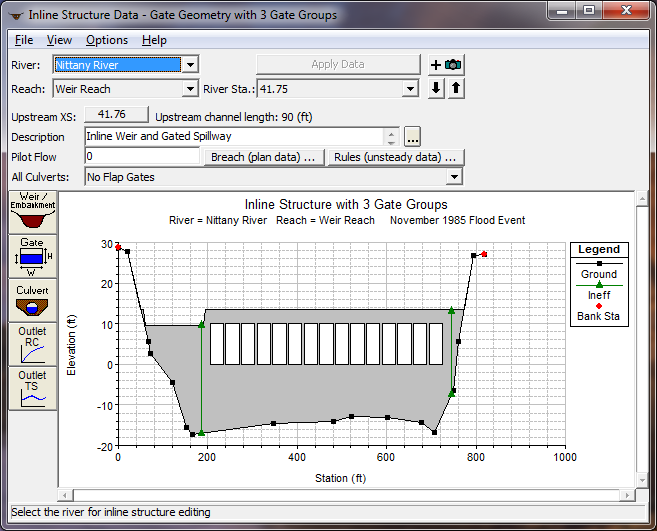
Inline Structure Data Editor
To add an inline structure to a model, the user must do the following:
- Select the river and reach that you would like to place this inline structure into. This is accomplished by first selecting a River, then selecting a specific reach within that river. The River and Reach selection buttons are at the top of the Inline Structure Data editor.
- Go to the Options menu at the top of the window and select Add an Inline Structure from the list. An input box will appear asking you to enter a river station identifier for locating this structure within the reach. After entering the river station, press the OK button and a copy of the cross section just upstream of this river station will appear on the screen. This cross section is used in formulating the inline structure crossing.
- Enter all of the data for the Inline structure. This data will include a Weir/Embankment profile, any gated spillways that you may be modeling, culverts, and/or outlet rating curves. All of the outlet types are optional, except the embankment profile of the inline structure. If the user does not enter any gated spillways, culverts, etc…, then the program assumes that there is only an inline weir.
- Once all of the Inline Structure data are entered, press the Apply Data button in order for the interface to accept the data. The editor can then be closed by selecting Exit from the File menu at the top of the window.
River, Reach, and River Station. The River and Reach boxes allow the user to select a river and reach from the available reaches that were put together in the schematic diagram. The river and reach labels define which river and reach the inline structure will be located in. The River Station tag defines where the structure will be located within the specified reach. The River Station tag does not have to be the actual river station of the structure, but it must be a numeric value. The River Station tag for the inline structure should be numerically between the two cross sections that bound the structure. Once the user selects Add an Inline Structure from the options menu, an input box will appear prompting you to enter a River Station tag for the new structure. After the River Station tag is entered, the cross section just upstream of the Inline Structure will be displayed on the editor.
Description. The description box is used to describe the Inline Structure location in more detail than just the river, reach and river station. This box has a limit of 256 characters. Only the first line of information is displayed, unless the button to the right of the box is pressed. Also, the first 40 characters of the description are used as a label for the Inline Structure plots and tables.
Pilot Flow. This option allows the user to put in a flow rate that will be used as a minimum flow release from the structure. If you have an inline structure in HEC-RAS, no cross section in the model can go dry during the simulation. While you can have a zero flow at the structure, the upstream and downstream cross sections must always have water in them. The pilot flow option is a simple way to ensure that there is always some minor flow going through the structure.
Breach (Plan Data). This button allows the user to define information for evaluating the breaching of this inline structure. The data is actually stored in the currently opened plan file. The editor can also be brought up from the plan editor. This option is only for unsteady flow modeling. To learn more about this option, see Chapter 8 "Performing an Unsteady Flow Analysis."
Rules (unsteady Data). This button brings up the Unsteady Flow Data and Boundary Conditions editor and allows the user to define a set of rules for controlling the gate openings. For more details on the Rules editor, please see Chapter 8, Performing an Unsteady Flow Analysis", in this manual.
All Culverts: This drop down selection box allows user to add flap gates to any culverts entered on the inline structure. The default is for "No Flap Gates", which means flow can go in both directions through the culverts. The other options include "Flaps prevent Negative Flow", which means flow can only go in the positive flow direction through the culverts (Downstream), and "Flaps prevent Positive Flow", which means flow can only go in the negative direction through the culverts (upstream).
Weir/Embankment Editor
The Embankment and Weir data are entered together, and are used to describe the embankment blocking the stream as well as any uncontrolled overflow weirs. To enter the weir and embankment data, press the Weir/Embankment button and the editor will appear (see figure below). The Weir/Embankment Data editor is similar to the Deck/Roadway editor for bridges and culverts. The data on the Weir/Embankment editor is the following:
Distance - The distance field is used to enter the distance between the upstream side of the Weir/Embankment (the top of the embankment) and the cross section immediately upstream of the structure. This distance is entered in feet (or meters for metric). 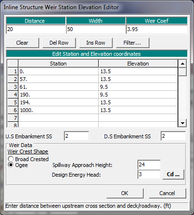
Weir and Embankment Data Editor
Width - The width field is used to enter the width of the top of the embankment along the stream. The distance between the top of the downstream side of the embankment and the downstream bounding cross section will equal the main channel reach length of the upstream cross section minus the sum of the weir/embankment "width" and the "distance" between the embankment and the upstream section. The width of the embankment should be entered in feet (meters for metric).
Weir Coefficient - Coefficient that will be used for weir flow over the embankment in the standard weir equation.
Station and Elevation Coordinates - This table is used to define the geometry of the Weir and the Embankment. The information is entered from left to right in cross section stationing. The user enters stations and elevations of the top of the embankment and weir. The stationing does not have to equal the stations in the bounding cross section, but it must be based on the same origin. Everything below these elevations will be filled in down to the ground. The Del Row and Ins Row buttons allow the user to delete and insert rows.
U.S. Embankment SS - This field is used to enter the slope of the road embankment on the upstream side of the structure. The slope should be entered as the horizontal to vertical distance ratio of the embankment.
D.S. Embankment SS - This field is used to enter the slope of the road embankment on the downstream side of the structure. The slope should be entered as the horizontal to vertical distance ratio of the embankment.
Weir Crest Shape - When submergence occurs over the weir there are two choices available to figure out how much the weir coefficient should be reduced due to the submergence. These two criteria are based on the shape of the weir. The first method is based on work that was done on a trapezoidal shaped broad crested weir (FHWA, 1978). The second criterion was developed for an Ogee spillway shape (COE, 1965). The user should pick the criterion that best matches their problem. If the user selects the Ogee Spillway shape, then some additional information is required. For an Ogee shaped weir the user must enter the "Spillway Approach Height" and the "Design Energy Head". The spillway approach height is equal to the elevation of the spillway crest minus the mean elevation of the ground just upstream of the spillway. The design energy head is equal to the energy grade line elevation (at the design discharge) minus the elevation of the spillway crest. In addition to these two parameters, the user has the option to have the program calculate the weir coefficient at the design discharge. This is accomplished by pressing the Cd button. Once this button is pressed, the program will compute a weir coefficient for the Ogee spillway based on the design head. During the weir calculations, this coefficient will fluctuate based on the actual head going over the spillway. The curves used for calculating the Ogee spillway coefficient at design head, and discharges other than design head, were taken from the Bureau of Reclamation publication "Design of Small Dams", Figures 249 and 250 on page 378 (Bureau of Reclamation, 1977).
Gated Spillway Editor
In addition to uncontrolled overflow weirs, the user can add gated spillways (this is optional). To add gated spillways to the structure, press the Gate button on the Inline Structure data editor. Once this button is pressed, the gated editor will appear as shown in the figure below (Except yours will be blank until you have entered some data).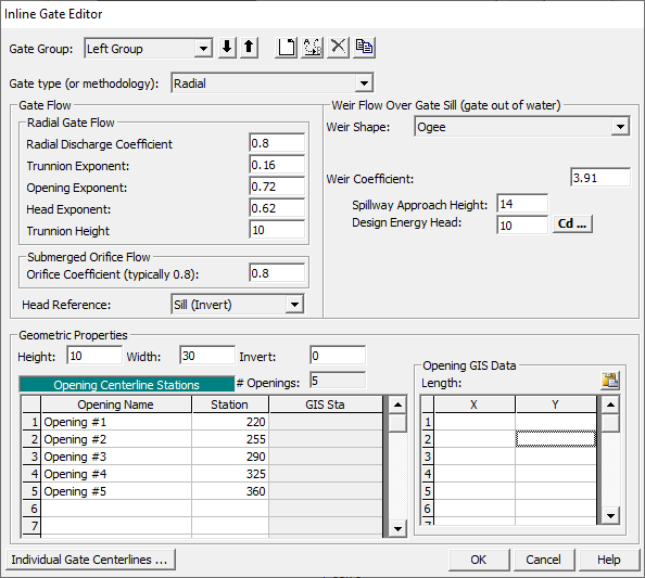
Gated Spillway Editor
The Gated Spillway editor is similar to the Culvert editor in concept. The user enters the physical description of the gates, as well as the required coefficients, in the Gated Spillway editor. The functionality of the gates is defined as part of the Unsteady Flow Data editor or the Steady Flow data editor (on a per profile basis). The following is a list of the data contained on this editor:
Gate Group - The Gate Group is automatically assigned to "Gate #1" the first time you open the editor. The user can enter up to 20 different Gate Groups at each particular river crossing, and each gate group can have up to 25 identical gate openings. If all of the gate openings are exactly the same, and any opened gates will be operated in the same manner, then only one gate group needs to be entered. However, if the user has gate openings that are different in shape, size, elevation, have different coefficients, or they will be operated differently, then additional Gate Groups must be added for each Gate type. To add an additional gate group you can either use the Add or Copy buttons. The Add button increments the Gate # and clears the gate editor. The Copy button increments the Gate # and makes a copy of the original Gate group data. Once a copy is made of the gate data, the user can change any of the existing gate information. Gate groups can be deleted by pressing the Delete button. Also, if the gates are identical, but the user wants to be able to open the gates to different elevations, then the user must have a separate gate group for each set of gates that will be opened to different elevations. In steady flow computations, the user can specify the number of gates in a group to be opened, but in unsteady flow computations all of the gates in a group are opened in exactly the same way (this is a limitation of our unsteady flow implementation of gates currently)
Geometric Properties of the Gates
Height - This field is used to enter the maximum possible height that the gate can be opened in feet (meters for metric).
Width - This field is used for entering the width of the gate in feet (meters).
Invert - This field is used for entering the elevation of the gate invert (sill elevation of the spillway inside of the gate) in feet (meters for metric). For overflow gates this is the lowest elevation that the gate will open to.
Opening Centerline Stations - This table is used for entering the centerline stationing of the gate openings. The user should enter a different centerline stationing for each gate opening that is part of the current gate group. All gate openings within the same gate group are exactly identical in every way, except their centerline stationing. As a user adds new centerline stationing values, the number of identical gates in the group is automatically incremented and displayed in the field labeled "# Openings".
Opening GIS Data – This table is used to enter X, Y coordinates for a line representing each gate. X, Y coordinates are only used when gates are connected to 2D Flow Areas. When a Gate is put into a Inline Structure of a 1D River Reach, then the X, Y coordinates are not needed or used. This table is only relevant to Lateral Structures and SA/2D Area Connections in which culverts will be connected to 2D Flow Area cells. It is not needed for pure 1D Inline Structures.
Gate Flow Coefficients
Gate Type (or methodology) - This field is used for selecting the type of gate. Five options are available for gate types: sluice (vertical lift gate), radial (tainter gate), Overflow (closed top), Overflow (open to the air), and User Defined Curves. Once a gate type is selected, the right hand side of the gate editor will change to show the required information for that gate type. Not all of the information is required for each gate type.
Discharge Coefficient - This field is used for entering the coefficient of discharge for the gate opening. This coefficient ranges from 0.6 to 0.8 for Radial gates and 0.5 to 0.7 for sluice gates. This coefficient is not required for overflow gates that are open to the air.
Trunnion Exponent - This field is used to enter the trunnion height exponent, which is used in the radial gate equation. The default value for this field is 0.0.
Opening Exponent - This field is used to enter the gate opening exponent, which is used in the radial gate equation. A default value of 1.0 is automatically set for this field.
Head Exponent - This field is used to enter the upstream energy head exponent, which is used in the radial gate equation. A default value of 0.5 is automatically set for this field.
Trunnion Height - This field is used for entering the height from the spillway crest to the trunnion pivot point. This data is only used for radial gates. See Chapter 8 of the Hydraulic Reference manual for more details on this variable.
Orifice Coefficient - This field is used to enter an orifice coefficient, which will be used for the gate opening when the gate becomes more than 80 percent submerged. Between 67 percent and 80 percent submerged, the program uses a transition between the fully submerged orifice equation and the free flow gate equations. When the flow is less than 67 percent submerged, the program uses the free flow gate equations. This coefficient is not required for overflow gates that are open to the air.
Head Reference – This field is used to select the reference point for which the upstream energy head will be computed from. The default is the gate sill (invert), which is normally used when the flow through the gate goes out into a channel. If the gate causes the flow to jet out freely into the atmosphere, then the head reference should be selected as the centerline elevation of the gate opening. If the gate crest is an ogee spillway crest, then the center of the gate opening should be used. Ogee spillway crests are normally designed to follow the shape of water jetting freely into the atmosphere.
Coefficients for Weir Flow over the Gate Sill
If a gate is opened to the point at which the top of the gate is no longer touching the water (or if an open air overflow gate is being used), then the flow through the gate is modeled as weir flow. The program will automatically transition from gate flow to weir flow when the upstream head is between 1.0 to 1.1 times the height of the gate opening. The following parameters are required to model weir flow through the gate opening.
Weir Shape - This parameter allows the user to select between a Broad Crested shape weir, an Ogee shaped weir, or a sharp crested weir. Depending on which shape is selected, the program will use a different submergence criteria during the calculations. In addition to the submergence criteria, if the user selects the Ogee shape, the program will bring up additional data entry fields that must be entered by the user. For the ogee weir shape, the additional fields are the Spillway Approach Height and the Design Energy Head, which are explained below. Once these fields are entered, the user should press the button labeled Cd. When this button is pressed, the program will compute a weir coefficient for the Ogee spillway based on the design head. During the weir calculations, this coefficient will fluctuate based on the actual head going over the gated spillway. The curves used for calculating the Ogee spillway coefficient at design head, and discharges other than design head, work taken from the Bureau of Reclamation publication "Design of Small Dams", Figures 249 and 250 on page 378 (Bureau of Reclamation, 1977).
Weir Method – This field is only available when the Sharp Crested Weir shape is selected. If a sharp crested weir shape is selected, then the user has three choices for defining the weir coefficient: User Entered Coefficient; Compute with Rehbock equation; and Compute with Kindsvater-Carter Equation. If the "User Entered Coefficient" option is selected, then the user simple enters a coefficient that will be used for weir flow through the gate, for all head ranges. If the "Rehbock equation" is selected, the user is asked to enter a spillway approach height (explained below), and the weir coefficient is then computed with the Rehbock equation. If the "Kindsvater-Carter equation" is selected, then the user must enter a spillway approach height, and also select which form of the Kindsvater- Carter equation will be used. The form of the Kindsvater-Carter equation is based on selecting one of eleven equations that are based on varying L/b. Where L is the width of the gate opening, and b is the top width of the approaching water upstream of the gate. If more than one gate is defined at a particular opening, you must figure out an average approach width for flow going to each gate.
Weir Coefficient - This field is used for entering a weir coefficient that will be used for the gate opening. This coefficient will only be used when the gate is opened to an elevation higher than the upstream water surface elevation. When this occurs, the flow through the gate is calculated as weir flow. If the Kindsvater-Carter equation is selected, then this field is used to select which form of the equation will be used to compute the coefficient.
Spillway Approach Height - The spillway approach height is equal to the elevation of the spillway crest minus the mean elevation of the ground just upstream of the spillway.
Design Energy Head - The design energy head is equal to the energy grade line elevation (at the design discharge) minus the elevation of the spillway.
User Defined Gate Curves
When the user selects "User Defined Curves" for the gate type, then the editor will change to look like the one shown in the figure below.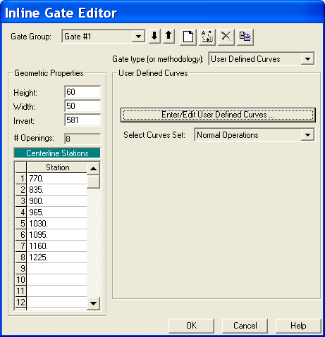
Gate Editor with User Defined Curves Selected.
As shown in the figure above, the user must select the button that says "Enter/Edit User Defined Curves". This will bring up another editor that allows the user to enter the curves into a table. The user is also required to give a name for each set of curves. More than one curve set can be entered, and the user can then select a different curve set for each gate group (if desired). Each curve set represents the head versus flow relationships for one single gate opening. When there are 2 or more identical gates in a group, each gate in the group gets the same curve set applied to it. When the "Enter/Edit User Defined Curves" button is pressed, a new editor will appear as shown in figure below.
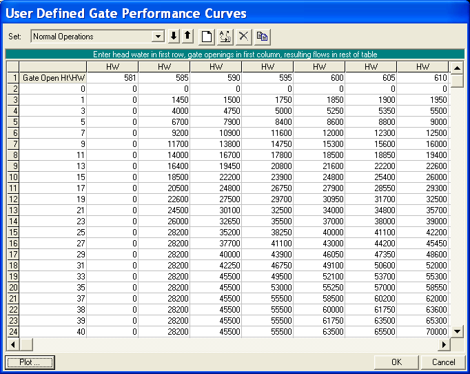
Editor for Entering/Editing Gate Curves.
As shown in figure above, the user enters gate openings in the first column. Headwater elevations are entered in the first row. The remaining fields are the corresponding flow for a given gate opening and upstream headwater elevation. To enter a new curve set, the user must first select the "New User Curve" button at the top of the editor. When this button is selected the user will be prompted to enter a name for the curve set. Other buttons at the top of the editor are for renaming the curve set, deleting the curve set, and copying the curve set to a new name. Once the curve set, or sets, are entered, the user simple selects a curve set for each gate group desired. The user also has the option to use curve sets for some gate groups and have the program calculate the flow from equations for others.
Once all of the data for the gates has been entered, the user needs to press the OK button for the data to be accepted. If the user does not want to use the new data, and would like to go back to the original data they had before entering the Gate Editor, press the Cancel button. If the user presses the OK button, this does not mean that the data is saved to the hard disk, it is only stored in memory and accepted as being good data. This data is part of the geometry data, and is stored in the geometric data file. The data can be stored to the hard disk by selecting one of the save options from the File menu of the Geometric Data window.
Culverts
User can also enter culverts at inline structures. Culverts can be entered as groups of identical culvert barrels (up to 25 barrels per culvert group), or the user can have up to 20 different culvert groups in which the culverts can be all kinds of shapes, sizes, elevations, roughness, etc… Culverts can compute flow in both directions, or user's have the option to have flap gates to prevent either negative flow (Flow upstream), or positive flow (Flow downstream) through the culverts. For details on the specific data to model a culvert, please review the section on culverts earlier in this chapter.
Outlet Rating Curves
If a user has an outlet type that does not exist in HEC-RAS, or cannot be modeled accurately with the available weirs, gates, and culverts, then an outlet rating curve can be used to model that specific outlet. The Outlet Rating curve can be based on upstream water surface elevations versus outlet flow, or it can be based on upstream total flow versus the flow through the outlet. This method does not take into account downstream tailwater influences on the flow rate.
Outlet Time Series
This option allows the user to specify a time series of flows to be used as an additional outlet through the inline structure. When this option is selected, the user enters a name to identify the outlet. For example, let's say you call the time series "Hydropower", which may represent flows going through a hydropower station at the structure. Then, the user can attach a flow hydrograph to the inline structure in the Unsteady Flow Data editor. This flow is then assigned to the user specified Outlet time Series specified on the inline structure. Only one, Outlet time series can be defined per inline structure, and only one hydrograph can be entered/attached to the inline structure in the unsteady flow data editor. If you have more than one time series you would like to use, combine them into one flow hydrograph outside of HEC-RAS, and then use that as the time series data.