Download PDF
Download page Lateral Structures (Weirs, Gated Spillways, Culverts, and Diversion Rating Curves).
Lateral Structures (Weirs, Gated Spillways, Culverts, and Diversion Rating Curves)
![]()
At any lateral structure HEC-RAS has the ability to model lateral weirs, gated spillways, culverts, diversion rating curves, and an outlet time series. The user can set up a single lateral weir, a weir and separate set of gates, a weir and group of culverts, or any combination of weir, gates, culverts, rating curves, and a time series outlet. The gated spillways can have either radial gates (often called tainter gates), vertical lift gates (sluice gates), overflow gates (open to the air or with a covered top), or user defined gate curves. The spillway crest of the gates can be modeled as either an ogee shape, broad crested weir, or sharp crested weir shapes. The culverts can be any of the available shapes from the standard HEC-RAS culvert capability. The diversion rating curve can be used alone, or in conjunction with the other hydraulic outlet types. The rating curve can be used to represent an entire structure or a particular outlet that could not be modeled with HEC-RAS. Lateral structures can be connected to storage areas, 2D Flow Areas, or another river reach.
The lateral structure option can also be used to model a levee. In general, the user should end their cross sections at the inside top of the levee, and then use the lateral structure option to represent the top of the levee along the stream. The area behind the levee could be represented with either a 2D Flow Area, storage area (or combination of interconnected storage areas), or another river reach. Water that goes above the levee will be modeled as weir flow. The user also has the option to evaluate levee breaching.
HEC-RAS now has the option to have georeferenced lateral structures. Under the menu item labeled GIS Tools, there is now a table option called Lateral Structure Centerlines Table. User can use the Measure Tool to draw a line that would represent the lateral structure geospatial X and Y coordinates, then paste those coordinates into the Lateral Structure Centerline Table (This is optional). If a user inserts geospatial coordinates for a lateral structure, not only will it be drawn geospatially correct, but HEC-RAS will figure out how elements (1D cross sections and 2D Face Points) are connected to the lateral structure based on its spatial location.
This section of the User's manual will describe how to enter the data for lateral weirs, gated spillways, culverts, lateral rating curves, and outlet time series. For information on general modeling guidelines and the hydraulic computations of lateral weirs, gated spillways, and culverts, please see Chapter 8 of the HEC-RAS Hydraulic Reference manual. To find out how to view specific results for a lateral structure, see Chapter 9 of this User's manual.
Entering and Editing Lateral Structure Data
Lateral weir, gated spillway, and culvert data are entered in a similar manner as bridge and culvert data. To enter a lateral structure, press the Lateral Structure button from the Geometric Data window. Once this button is pressed, the Lateral Structure Data editor will appear as shown in the figure below (except yours will be blank until you have entered some data).
To add a lateral structure to a model, the user must do the following:
- Select the river and reach that you would like to place this lateral structure into. This is accomplished by first selecting a River, then selecting a specific reach within that river. The River and Reach selection buttons are at the top of the Lateral Structure Data editor.
- Go to the Options menu at the top of the window and select Add a Lateral Structure from the list. An input box will appear asking you to enter a river station identifier for locating this structure within the reach. The river station you enter will represent the location of the upstream end of the lateral structure. The river station must be unique, and should be numerically between the river station values of the upstream cross section and the next section downstream. After entering the river station, press the OK button and a profile plot of the channel invert and cross sections in the vicinity of the lateral weir/spillway will be displayed.
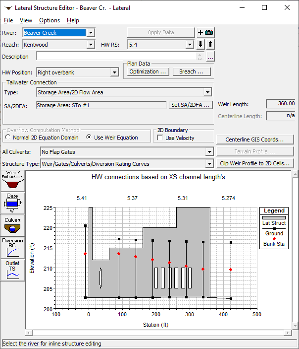
Lateral Weir, Gated Spillway, and Culvert Editor
- Enter all of the data for the Lateral Weir, Gated Spillways, Culverts, Diversion Rating Curves, and Outlet Time Series. All of the outlet types are optional, and can be mixed and matched to form a single lateral structure. If the user does not enter any gated spillways, culverts, rating curves, or outlet time series, then the program assumes that there is only a lateral weir. If the user wants to enter only gated spillways, culverts, or a rating curve, and no lateral weir, they must still enter a weir embankment.
- Once all of the data are entered, press the Apply Data button in order for the interface to accept the data. The editor can then be closed by selecting Exit from the File menu at the top of the window.
- If any gated spillways were entered, the user must go to the Steady or Unsteady Flow Data Editor to control the gate settings for each individual event. If an outlet time series was entered, then the user must attach a flow hydrograph to the lateral structure in the Unsteady Flow Data editor.
The user can have up to two lateral structures defined between any two given cross sections. However, the lateral structure must be placed on opposite sides of the channel (i.e. one on the left and one on the right), and the river stations of each lateral structure must be different (though still contained within the two cross section river station values). Also, any lateral structure can be longer than the distance between cross sections. The user can have a lateral structure that extends downstream, encompassing up to 100 cross sections. If you have a lateral structure that is longer than that, you must break it up into separate lateral structures.
River, Reach, and River Station. The River and Reach boxes allow the user to select a river and reach from the available reaches that were defined in the schematic diagram. The river and reach labels define which river and reach the lateral structure will be located in. The Head Water River Station (HW RS) tag defines where the structure will be located within the specified reach. The River Station tag does not have to be the actual river station of the structure, but it must be a numeric value. The River Station tag for the lateral structure should be numerically between the two cross sections that bound the upstream end of the structure. Once the user selects Add a Lateral Structure from the options menu, an input box will appear prompting you to enter a River Station tag for the new structure. After the River Station tag is entered, a profile plot of the reach thalweg will be displayed for the bounding cross sections in the graphic window. The river and reach in which the lateral structure is defined is considered to be the headwater side of the structure. Whatever the user connects the lateral structure to is considered to be the tailwater side of the structure.
Description. The description box is used to describe the Lateral Structure location in more detail than just the river, reach and river station. This box has a limit of 256 characters. Only the first line of information is displayed, unless the button to the right of the box is pressed. Also, the first 40 characters of the description are used as a label for the Lateral Structure plots and tables.
HW Position. The headwater position box is used to define where the lateral structure is located spatially within the reach that it is defined. The user can select one of the following: Left overbank; Next to left bank station; Next to right bank station; and Right overbank. When the user selects "Left overbank", the weir is assumed to be located at the left end (beginning cross section station) of the cross section data, looking in the downstream direction. When the user selects "Next to left bank station", the weir is assumed to be located on the left edge of the main channel. When the user selects "Next to right bank station", the weir is assumed to be located on the right edge of the main channel. When the user selects "Right overbank", the weir is assumed to be located at the right end of the cross section data.
Tailwater Connection. This area of the editor is used to define what the lateral structure is connected to (i.e. where the water leaving from the main river will be going). A lateral structure can be connected to a storage area; 2D Flow Area; cross sections in another river reach; or nothing at all (defined as leaving the system). To set the tailwater connection, first select the connection type from the area labeled: Type. Then, depending on the type of tailwater connection, other information may be required. If the tailwater connection type is Out of the System, then no other information is required. If the tailwater connection type is a Storage Area/2D Flow Area, then the user is required to select a storage area or a 2D Flow Area from a drop down list of the currently defined storage areas. If the tailwater connection type is Cross Sections of a River/Reach, then the user is required to select the river, reach, and range of cross sections that the lateral structure is connected to. The tailwater connection can be to a single cross section (all the flow goes to one point), or it can be set to a range of cross sections (the flow will be distributed over the range of cross sections). In addition to the cross section(s) the user must define if the connection is on the right over bank; next to the right bank station; next to the left bank station, or on the left overbank. Water can also flow in the reverse direction through a lateral structure if the connected to location has a higher water surface than the from location. Reverse flow gets labeled as negative flows for a lateral structure.
Structure Type. This field is used to select the type of routing that will be used for this structure. There are two options, Weir/Gates/Culverts/ Diversion Rating Curves (the default) and Linear Routing. The default option is where the program calculated the flow across the structure by performing detailed hydraulic calculations for the weir, gated spillways, culverts, and any rating curve. The second option, Linear Routing, is a simplified method in which the user just puts in a linear routing coefficient. This coefficient can vary between 0.0 and 1.0, with 1.0 representing sending the maximum flow over the structure and 0.0 representing no flow. The linear routing method is a simple storage accounting method. This method can be very useful when the user has many lateral structures connected to storage areas, and a detailed flow calculation over each structure is not necessary. Also, the linear routing method is computationally faster and more stable. Typical values for the linear routing coefficient are from 0.05 to 0.2. However, this coefficient needs to be calibrated.
Culvert Flap Gates. The drop down box right above the Structure Type pertains to having flap gates on culverts. This option only affects the flow through the culverts, not the weir or the gated structures. The options are no flap gates (default), Flaps prevent negative flow, and flaps prevent positive flow. No flap gates means that flow is allowed to go in both directions through the culvert. The "Flaps prevent negative flow" option means that flow can only go in the positive flow direction through the culverts. Positive flow is assumed to be taking flow away from the river for a lateral structure. Therefore, the "Flaps prevent negative flow" option would allow water to go away from the main river through the culverts, but not back into the river. The final option, "flaps prevent positive flow", would only allow water to come into the main river through the culverts, but not away from the main river.
Overflow Computation Method. This option is used to control what equations are used to compute the flow across a Lateral Structure. By default the "Weir" equation is used. However, if the Lateral Structure is connected to a 2D Flow Area, then there is the option to use the 2D Flow equations to figure out how much flow is going across the Lateral Structure, and in which direction. When the 2D Flow Equations overflow method is selected, an average water surface elevation is computed one the 1D river side, in front of each 2D cell that is connected with the Lateral Structure. This water surface is then applied as a stage boundary condition for each individual cell of the 2D area. So, if water is above the weir profile, and the elevation is higher in the 1D river than the 2D cell, then water will go from the 1D river to the 2D cell. If the 2D cell is higher than the 1D river, then water will go from the 2D cell to the 1D river. If the water is below the elevation of the weir, then the flow is zero for that cell.
2D Boundary. This option is used only when a Lateral Structure is connected to a 2D Flow Area. In general for this type of flow connection, flow is computed across the structure and passed into and out of the 2D cells, and no velocity is considered at the face. If this option is turned on, in addition to flow, a velocity is computed and applied to the face of the 2D cells. By default this is off, which produces a more stable solution, but less velocity accuracy. If turned on, it will produce more accurate flow velocities into the 2D area, but may be less stable.
Optimization. This option is for steady flow modeling, or the initial conditions of an Unsteady flow model. When modeling in a steady flow mode (or unsteady flow initial conditions), the user can have the software figure out how much flow will leave through the lateral structure, and how much will continue on downstream. This calculation requires an iterative solution. Pressing the Optimization button brings up an editor that allows the user to turn the optimization option on. When optimization is not turned on, the program will assume all of the water is still going downstream, though it will calculate what could have gone out the lateral weir based on the computed water surface. When optimization is turned on, the software calculates the flow out of the lateral structure, reduces the flow in the main river, and then recalculates the profile in the main river. This operation continues until there is a balance between the calculated and assumed flows for the main river.
Breach. This button allows the user to define information for evaluating the breaching of this lateral structure. The data is actually stored in the currently opened plan file. The editor can also be brought up from the plan editor. This option is only for unsteady flow modeling. To learn more about this option, see Chapter 16 "Advanced Features for Unsteady Flow Routing."
Weir/Embankment Editor
The Embankment and Weir data are entered together, and are used to describe the embankment in which the outlets will be placed, as well as any uncontrolled weirs. To enter the weir and embankment data, press the Weir/Embankment button and the editor will appear as shown in the figure below. 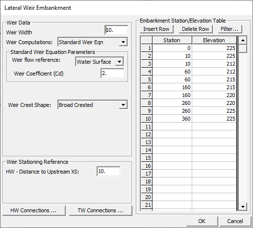
Lateral Weir/Embankment Editor
The Lateral Weir/Embankment Data editor is similar to the Deck/Roadway editor for bridges and culverts. The data on the Weir/Embankment editor is the following:
Weir Width - The width field is used to enter the width of the top of the embankment. This value will only be used for graphical plotting, and does not have any effect on the computations. The width of the embankment should be entered in feet (meters for metric).
Weir Computations – This field allows the user to select either the standard weir equation or Hager's lateral weir equation. When the standard weir equation is selected, the user will also need to enter a weir flow reference head, and a weir coefficient. If Hager's lateral weir equation is selected, the user must also enter: default weir coefficient; weir average height; an average bed slope, and a weir angle in degrees if it is anything other than parallel to the stream.
Weir flow reference - This value is used to select whether weir flow is computed by using the energy gradeline or the water surface from the cross sections. The default is to use the energy gradeline.
Weir Coefficient - Coefficient that will be used for weir flow over the embankment in the standard weir equation.
Weir Crest Shape - When submergence occurs over the weir/embankment there are four choices available to figure out how much the weir coefficient should be reduced due to the submergence. These four criteria are based on the shape of the weir. The first method is based on work that was done on a trapezoidal shaped broad crested weir (FHWA, 1978). The second criterion was developed for an Ogee spillway shape (COE, 1965). The third is for a sharp crested weir. The last selection is when there really is no weir, and flow is just traveling overland. This is called a "Zero Height" weir. The user should pick the criterion that best matches their problem. If the user selects the Ogee Spillway shape, then some additional information is required. For an Ogee shaped weir the user must enter the "Spillway Approach Height" and the "Design Energy Head". The spillway approach height is equal to the elevation of the spillway crest minus the mean elevation of the ground just upstream of the spillway. The design energy head is equal to the energy grade line elevation (at the design discharge) minus the elevation of the spillway crest. In addition to these two parameters, the user has the option to have the program calculate the weir coefficient at the design discharge. This is accomplished by pressing the Cd button. Once this button is pressed, the program will compute a weir coefficient for the Ogee spillway based on the design head. During the weir calculations, this coefficient will fluctuate based on the actual head going over the spillway. The curves used for calculating the Ogee spillway coefficient at design head, and discharges other than design head, were taken from the Bureau of Reclamation publication "Design of Small Dams", Figures 249 and 250 on page 378 (Bureau of Reclamation, 1977).
HW Distance to Upstream XS - This field is used to enter the distance between the upstream end of the Weir/Embankment (based on where the user will start to enter the embankment data) and the cross section immediately upstream of the structure. This distance is entered in feet (or meters for metric).
TW Flow Goes – If the lateral structure is set to send flow to another river reach, this field will be active. This field is used to select where the flow will go to in the tailwater (TW) reach. Flow can be set to go into a single point, or it can be set to go over a range of cross sections.
TW Distance to Upstream Cross Section – If the lateral structure is set to send flow to another river reach, this field we be active. This field is used to enter a distance between the connected tailwater cross section, and the actual location in which the weir begins to connect. Default value is zero, meaning the weir starts at the selected tailwater cross section and continues downstream from there. Only positive values can be entered. Any number greater than zero means that the weir connection starts downstream of the connected cross section, by the user entered distance.
Weir Station and Elevation - This table is used to define the geometry of the Weir and the Embankment. The information is entered from upstream to downstream in stationing. The user enters stations and elevations of the top of the embankment and weir. The stationing is relative, so it can be started at any number (i.e. 0, 100, etc…). The user enters stations and elevations from the upstream end to the downstream end of the lateral structure. Everything below these elevations will be filled in to the ground. By default, the lateral structure will be lined up with the river/reach by comparing the stationing entered with the reach lengths of the river/reach. If the lateral structure is connected to the right overbank of the reach, then the right overbank reach lengths are used. If the lateral structure is connected to the right or left bank station of the main channel, then the main channel reach lengths will be used. The Filter button allows the user to filter the station and elevation points in order to reduce the total number of points. This feature is often used when a lateral weir is used to represent a natural overflow area, and the data has come from a GIS.
Headwater Connections – This table will by default show the weir stationing that intersects with the cross sections in the river/reach that the structure is defined in. The software automatically aligns the weir with the cross sections in the reach based on the weir stationing and the reach lengths in the cross sections (either left overbank, main channel, or right overbank reach lengths). However, if the user does not like how the defined weir intersects with the cross sections in the reach, they can define their own intersection points by entering the desired weir stationing to intersect with each of the cross sections in the reach. Water surface elevations for the lateral structure will then be interpolated based on the user entered stationing.
Tailwater Connections – This table can be used to line up the weir to either a 2D Flow Area or cross sections in another reach in a user controlled manner. By default the weir is automatically lined up to any 2D Flow Area or cross sections of another river reach that it is connected too. However, this editor will allow users to hand change the connection locations to the 2D Flow Area Face points, or cross section river station locations of the river reach. The user can select to use "User specified intersections", which will allow them to describe where the stationing of the weir hits the tailwater cross sections or 2D Flow Area Face points. If this option is used the user must completely define where the entire length of the weir intersects the various tailwater cross sections or 2D Flow Area.
If Hager's Lateral weir equation is selected from the "Weir Computations" field, then the following additional fields will appear:
Default Weir Coefficient (Cd) – This weir coefficient will be used for the first iteration of trying the Hager lateral weir equation. The equation is iterative, and requires hydraulic results in order to make a weir coefficient calculation. The default weir coefficient is only used for the first guess at the hydraulic computations.
Weir Average Height – This field is used for entering the average height of the weir above the ground.
Average Bed Slope (Optional) – This field is used for entering the average slope of the stream bed in the reach of river that contains the lateral weir. If the use does not enter this field, the HEC-RAS program will compute the slope by estimating an average bed elevation for each cross section, then computing the slope of the average bed elevation. Average bed elevation of an irregular cross section is obtained by subtracting hydraulic depth from the water surface elevation.
Weir Angle in Degrees (Optional) – This field can be used to enter and angle for the weir. If the weir is parallel to the stream, the angle is assumed to be zero. If the weir is angled inwards towards the center of the river, an angle (beta) is required. This is used for channels that have a contraction, and weir flow is allowed to go over the contracted section. A diagram showing the angle (beta) is shown below: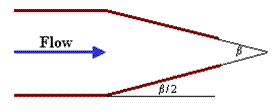
Gated Spillway Editor
In addition to uncontrolled overflow weirs, the user can add gated spillways (this is optional). To add gated spillways to the structure, press the Gate button on the Lateral Weir and Gated Spillway data editor. Once this button is pressed, the lateral gated editor will appear as shown in the figure below (except yours will be blank until you have entered some data).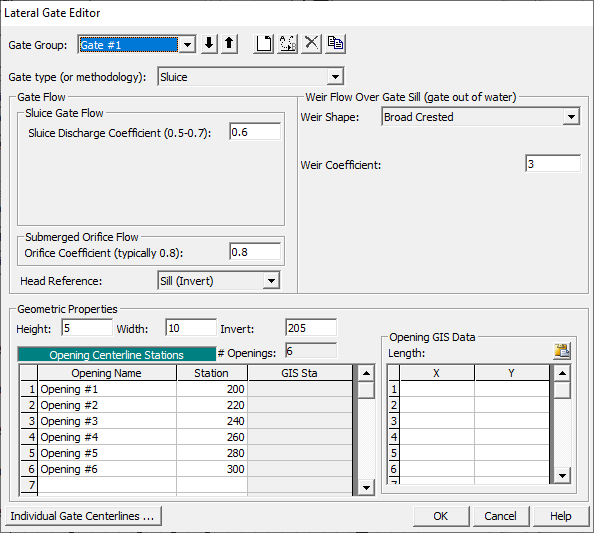
Lateral Gated Spillway Editor
The Gated Spillway editor is similar to the Culvert editor in concept. The user enters the physical description of the gates, as well as the required coefficients, in the Gated Spillway editor. The functionality of the gates is defined as part of the Unsteady flow Data, or the Steady Flow data (on a per profile basis). The data for modeling a gate in a lateral structure is the same as the data for modeling a gate in an inline structure. Please refer to the previous section on inline structures to get a detailed explanation of the data for the gate editor.
Culvert Editor
In addition to the lateral weir and gates, the user can also enter lateral culverts. To add culverts to the structure, press the Culvert button on the lower left side of the editor. When this option is selected the following window will appear.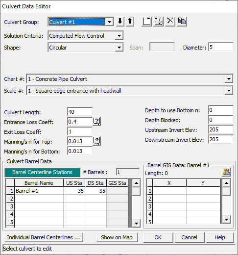
Culvert Editor for Lateral Culverts
The required culvert data is the same as for an inline culvert. To see an explanation of each field on the editor, review the information on culverts found earlier in this chapter. The only difference is that the centerline stationing of each culvert is based on the stationing entered in the Weir/Embankment editor.
Diversion Rating Curve Editor
Diversion rating curves are used to remove flow from a main river. The diversion, rating curve can be used in conjunction with a lateral weir, gated structures, and culverts, or it can be used alone.
To add a diversion, rating curve to the system, press the "Diversion Rating Curve" button on the left hand side of the Lateral Structure editor. When this button is pressed, the following editor will appear: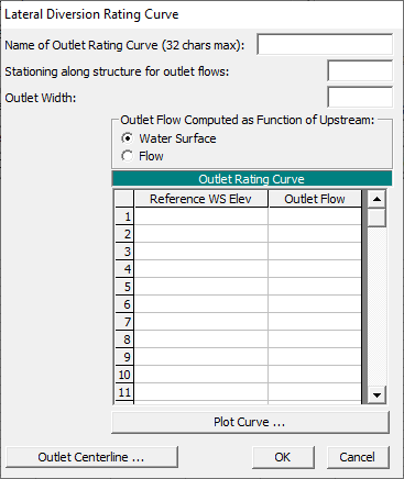
Lateral Rating Curve Editor
The user first selects the type of rating to be used: channel water surface versus diverted flow or channel flow versus diverted flow. Next, the distance between the location of the diversion and the cross section just upstream of the structure must be entered in order to locate the diversion. Finally, the user enters the actual rating curve. The curve is entered as the amount of flow leaving, verses the elevation of the water in the main river or flow in the main river. NOTE: This rating curve does not take into account any influence of the tailwater elevation in order to reduce the flow.
Outlet Time Series
This option allows the user to specify a name for an Outlet time series. Then a Flow Hydrograph can be specified for the Lateral Structure in the Unsteady Flow Data editor. The flow time series will be labeled in the output based on the user entered name for the Outlet Time series.
Linear Routing Option
The user can choose to use a linear routing option instead of entering structure information and having the program compute the flow from the structures. The linear routing option is selected by going to the Structure Type pull down and selecting "Linear Routing" from the list. This option uses a coefficient times the difference in available storage between the too and from connection. When this option is selected, a linear routing button will appear on the left side of the window. Selecting the linear routing button will bring up the following window: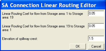
Simple Spillway Data Editor
The equation used for the linear routing computations is the following:
Q = K (Available Storage)/hour
Where:
Q = Flow per hour
K = Linear Routing Coefficient (0.0 to 1.0)
Available Storage = ∆Z (Surface Area)
Surface Area = surface area of receiving storage area.
∆Z is the difference between the headwater and tailwater water surface elevation on each side of the lateral structure. If both water surfaces are below the spillway crest elevation, then the flow is zero. If one water surface is above the spillway elevation and the other is not, then ∆Z is compute as the water surface above the spillway crest minus the spillway crest elevation.
The flow is computed in cfs per hour. If the user selected time step is not 1 hour, then the flow for the time step is compute by multiplying the flow by the ratio of the user entered time step divided by 1 hour.
As shown in the Linear Routing editor, the user must enter a linear routing coefficient for both the positive and negative flow directions. Additionally, the minimum elevation of the spillway crest must be entered. If both water surfaces go below the spillway crest, no flow is passed over the structure. Also, the user must enter the HW Distance to Upstream XS, which allows the program to figure out where the location of the lateral connection with respect to the upstream cross section. This location will be used for interpolating water surface elevations on the river side of the connection.