Download PDF
Download page Multiple Bridge/Culvert Openings.
Multiple Bridge/Culvert Openings
HEC-RAS has the ability to model multiple bridge and/or culvert openings at any individual river crossing. Types of openings can consist of bridges, culvert groups (a group of culverts is considered to be a single opening), and conveyance areas (an area where water will flow as open channel flow, other than a bridge or culvert opening). Up to seven openings can be modeled at a given location, and any combination of bridges and culvert groups can be used. Conveyance type openings can range from zero to a maximum of two, and the conveyance areas must be located on the far left and far right of the river crossing.
An example multiple opening is shown in Figure 5-25. As shown in this example, there are three types of openings: a conveyance area (left side, labeled as opening #1), a bridge (labeled as opening #2), and a culvert group (labeled as opening #3). During low flow conditions, flow will be limited to the bridge opening. As flow increases, the culverts will begin to take some of the flow away from the bridge opening. The conveyance area was defined as ineffective flow (no conveyance) until the water surface goes above the top of the bridge. This was accomplished by setting blocked ineffective flow areas. In this example, three blocked ineffective flow areas were established: one to the left of the bridge (which encompasses the whole conveyance area), one between the bridge and the culvert group, and one to the right of the culvert group.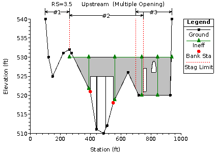
Figure 5 25 Example Multiple Opening River Crossing
Entering Multiple Opening Data
Multiple opening data are entered in the same manner as any other bridge or culvert crossing. In general, the user should perform the following steps to enter multiple opening data:
- Press the Bridge/Culvert button on the Geometric Data window.
- Select the river and reach in which you would like to place the multiple opening river crossing. This is accomplished from the River and Reach boxes near the top of the window.
- Select Add a Bridge and/or Culvert from the Options menu of the bridge and culvert editor. Enter the river station at which you want to place the multiple opening crossing. Once you have done this, the two cross sections that bound this river station will appear in the window. These two cross sections, along with the bridge and culvert information, will be used to formulate the two cross sections inside the multiple opening river crossing.
- Enter the deck and road embankment data by using the Deck/Roadway editor.
- Enter any piers or sloping abutments that are required.
- Select the Bridge Modeling Approach button and enter a set of coefficients and modeling approaches for each bridge opening.
- Enter Culvert data for any culvert openings.
- Select the Multiple Opening Analysis button on the bridge and culvert editor. Enter the types of openings and their station limits. Start at the left most station of the crossing and work your way to the right end. This is explained in greater detail under the section entitled "Defining the Openings".
Deck/Road Embankment Data. There can only be one deck and road embankment entered for any bridge and/or culvert crossing. The deck editor is used to describe the area that will be blocked out due to the bridge deck and road embankment. As shown by the gray shaded area in Figure 5-25, the deck and roadway data are used to block out area around the bridge as well as around the culverts. In the area of the bridge, high and low chord information is entered in order to define the top of road as well as the bridge opening. In the area of the culverts, the high chord information is entered to define the rest of the top of the road embankment. However, the low chord information can be left blank, or set to elevations below the ground, because the culvert data define the culvert openings.
Piers and abutments. All piers are entered from the pier editor, which was described previously under bridge data. The number of bridge openings has no impact on how pier data are entered. Piers are treated as separate information. Once the user establishes that there is more than one bridge opening, the program is smart enough to figure out which piers go with which opening. If any sloping abutment data are required for a bridge opening, it can be entered as described previously under the bridge data section.
Bridge Modeling Approach. A bridge modeling approach and coefficient set must be established for at least one bridge opening. If there is more than one bridge opening, and the user has only established a single coefficient set and bridge modeling approach, those data will be used for all of the bridge openings. The user can establish a different set of coefficients and modeling approaches for each bridge opening. 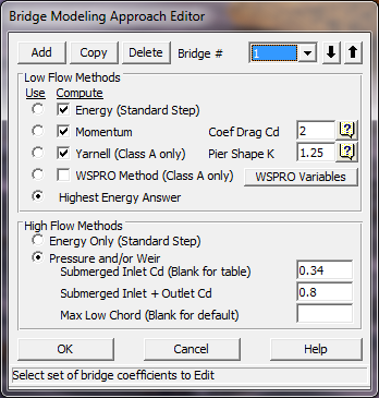
Figure 5 26 Bridge Modeling Approach Editor
As shown in Figure 5-26, the user must enter information under the Bridge Modeling Approach editor for at least one bridge Opening. Bridge openings are referred to as Bridge # 1, Bridge # 2, etc., up to the number of bridge openings. Bridge # 1 represents the left most bridge opening while looking in the downstream direction. Bridge # 2 represents the next bridge opening to the right of Bridge # 1, and so on. The user can enter additional coefficient sets and modeling approaches by selecting either the Add or Copy button. If either of these buttons is selected, the Bridge # will automatically be incremented by one. The user can then enter or change any of the information on the editor for the second bridge opening. Any bridge opening that does not have a corresponding coefficient set and modeling approach, will automatically default to what is set for Bridge # 1.
Culvert Data. Culvert information is added in the same manner as described in the previous section called "Entering and Editing Culvert Data." Culverts will automatically be grouped based on their stationing.
Defining the Openings
Once all of the bridge and/or culvert data are entered for a multiple opening river crossing, the last step is to define the number and type of openings that are being modeled. This is accomplished by pressing the Multiple Opening Analysis button on the Bridge/Culvert Data editor. Once this button is pressed, an editor will appear as shown in Figure 5-27 (except yours will be blank the first time you bring it up).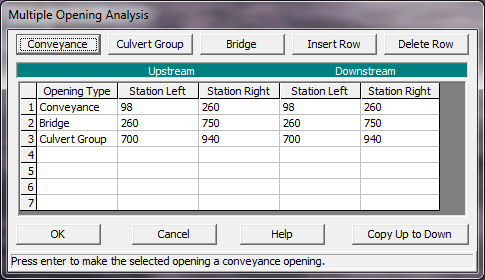
Figure 5 27 Multiple Opening Analysis window
The user selects from the three available opening types: Conveyance; Culvert Group; and Bridge. Openings must be established in order from left to right, while looking in the downstream direction. In addition to establishing the number and types of openings, the user must also enter a Station Left and a Station Right for each opening. These stations are used to establish limits for each opening as well as stagnation points. Stagnation points are the locations at which flow separates (on the upstream side) from one opening to the next adjacent opening. Stagnation points can either be set to fixed locations or they can be allowed to migrate within limits.
As shown in Figure 5-27 (numerical representation) and Figure 5-25 (graphical representation), there are three openings established in this example. The first opening is defined as a conveyance area, and it ranges from station 98 (the left most station of the section) to station 260. That means that any water in this area will be treated as normal open channel flow, and the water surface will be calculated by performing standard step calculations with the energy equation. The second opening is the bridge opening. This opening has a left station of 260 and a right station of 740. This bridge will be modeled by using the cross section data, bridge deck, and pier information that lie within these two stations (260 and 740). The bridge coefficients and modeling approach for this opening will be based on the data entered for bridge opening #1, since it is the first bridge opening. The third opening is a culvert group. This opening has a left station of 650 and a right station of 940. Any culverts that lie within these stations will be considered as being in the same culvert group.
Notice that the right station of the bridge opening overlaps with the left station of the culvert group. This is done on purpose. By overlapping these stations, the user is allowing the program to calculate the location of the stagnation point between these two openings. This allows the stagnation point to vary from one profile to the next. In the current version of the HEC-RAS software, stagnation points are allowed to migrate between any bridge and culvert group openings. However, stagnation points must be set to a fixed location for any conveyance opening type. A more detailed explanation of stagnation points, and how the program uses them, can be found in the HEC-RAS Hydraulics Reference manual, under the section on Multiple Openings (Chapter 7).
Once the user has entered all of the information into the Multiple Opening Analysis window, simply press the OK button to accept the data.
Multiple Opening Calculations
Multiple opening calculations are computationally intensive. An iterative solution approach is used, by which the amount of flow through each opening is adjusted until the computed upstream energies of each opening are balanced within a predefined tolerance. The general approach of the solution scheme is as follows:
- The program makes a first guess at the upstream water surface by setting it to the computed energy of the cross section just downstream of the bridge.
- The program sets an initial flow distribution. This is accomplished by first calculating the amount of active flow area in each opening, based on the water surface from step one. The program then apportions the flow by using an area weighting (i.e., if an opening has 40 percent of the active flow area, then it will receive 40 percent of the flow).
- Once a flow distribution is established, the program then calculates the water surface and energy profiles for each opening, using the estimated flow.
- Once the program has computed the upstream energy for each opening, a comparison is made between the energies to see if a balance has been achieved (i.e., all energies are within the predefined tolerance). If the energies are not within the set tolerance, the program re-distributes the flow based on the computed energies.
- The program continues this process until either the computed energies are within the tolerance or the number of iterations reaches a pre-defined maximum. The energy balance tolerance is set as 3 times the user entered water surface calculation tolerance (The default is 0.03 feet or 0.009 meters). The maximum number of iterations for multiple opening analysis is set to 1.5 times the user entered maximum number of iterations from the normal water surface calculations (the default is 30 for multiple openings).
A more detailed discussion of how the program performs the multiple opening analyses can be found in Chapter 7 of the HEC-RAS Hydraulic Reference manual.