Download PDF
Download page User Enter Breach Data.
User Enter Breach Data
If the "User Entered Data" Breaching Method is selected, then the following data must be entered for the breaching analysis:
Center Station - This field is used for entering the centerline stationing of the final breach.
Final Bottom Width - This field is used to enter the bottom width of the breach at its maximum size.
Final Bottom Elevation - This field is used to enter the elevation of the bottom of the breach after it has been fully developed.
Left Side Slope - This is the left side slope of the trapezoidal breach.
Right Side Slope - This is the right side slope of the trapezoidal breach.
Breach Weir Coef – This field is used for entering a weir coefficient for the breach area. For an overtopping failure, or when the top of a piping failure collapses, the program uses a weir equation to calculate the flow through the breach. Suggested range of values are 2.0 to 3.2, with 2.6 as a default value for most earth dams.
Breach Formation Time (hrs) - This field is used to enter the breach development time in hours. This time represents the duration from when the breach begins to have some significant erosion, to the full development of the breach.
Failure Mode - This option allows the user to choose between two different failure modes, an Overtopping failure and a Piping failure.
Piping Coefficient - If a piping failure mode is selected, the user must enter a piping coefficient. This coefficient is an Orifice coefficient, which is used while flow is coming out of the dam in a piping mode. Typical Orifice coefficients for a true designed orifice are around 0.8. However, for a piping breach, the coefficient should be lower to represent all of the additional energy losses occurring.
Initial Piping Elev. - If a piping failure mode is selected the user must enter an initial piping elevation. This elevation should be entered as the center of the piping flow while the breach develops.
Trigger Failure At - This field is used to select one of three trigger methods for initiating the breach. The three trigger methods are: a water surface elevation, a water surface elevation plus a duration of time that the water is above that elevation, and a specific time and date.
WS Elev - If the user selects water surface elevation for the failure trigger mode, then an additional field labeled WS Start must be entered. This field represents the water surface elevation at which the breach should begin to occur.
WS Elev+Duration – If the user selects WS Elev+Duration for the trigger mechanism of the failure, then they have three additional fields of data to enter. The first variable is Threshold WS. This variable is the water surface elevation at which the program starts to monitor the flow for duration above this water surface. The second variable is Duration above Threshold. This variable is used to specify the duration that the water surface must be above the threshold water surface elevation before the failure will initiate. The final variable, Immediate initiation WS, is used to instruct the program to begin the breach if the water surface in the structure reaches this elevation or higher, regardless of the duration requirement. This last field is optional.
Set Time - If the user selects the Set Time option, then a starting date and time to initiate the breach must be entered.
Breach Progression - In addition to all of the main breach information, the user also has the option to enter a user specified Breach Progression curve. By default the breach progression is assumed to be linear between the breach initiation and the full breach size (Full Formation Time). The user enters their breach progression curve by selecting the Breach Progression tab. When this tab is selected, the editor will look like the following (Figure 7-59):
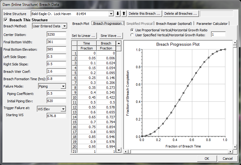
Figure 7 59. Dam Breach Editor with User Specified Breach Progression Tab Selected
As shown in Figure 7-59, the user enters a Time Fraction (from zero to 1.0) and a Breach Fraction (from zero to 1.0). The user-entered data is plotted in the graphic next to the table. The breach progression curve is then used during the breach formation time to adjust the growth rate of the breach.
NOTE: Previous to version 4.2, the horizontal and vertical growth rate of the breach was base on reaching the maximum breach depth and width at the user entered "Breach Formation Time". This means if a user put in breach dimensions of 400 ft wide and 100 ft deep, over a period of 2 hours, the horizontal growth rate was 200ft/hr and the vertical growth rate was 50 ft/hr. While this was generally ok for Dam breaches, it was not ok for levee breaching, in that levee breaches are much wider than they are tall. As of version 4.2, RAS computes the breach growth rate based on the breach "Final Bottom Width" and the user entered "Breach Formation Time". Then this same breach growth rate is used for the vertical down cutting of the breach. So in the previous example of a 400 ft breach bottom width and a 2 hour breach development time, the growth rate is 200 ft/hr, which is used for both the down cutting and widening rates. User's can change the vertical Breach Growth Rate by entering a value other than 1.0 under the option labeled "User Specified Vertical/Horizontal Growth Ratio" and the Breach Progression Tab. If a user enters a value of 0.5, that means you want the vertical growth rate to be half of what the Horizontal growth rate gets computed to be.
WARNING: The breach growth rate change described in the previous paragraph will generally results in RAS version 4.2 and newer yielding a higher peak flow through the breach, than versions 4.1 and older. If the user wants the same results as version 4.1 and older, you must compute a vertical/horizontal growth rate that will results in the breach reaching its maximum width and depth at the end of the breach formation time. For example (assuming an overtopping breach), if you specified a 400 ft breach bottom width and a 2 hour breach formation time, this is a horizontal growth rate of 200 ft/ hour. However, if you Dam is only 100 ft high, then to reproduce the version 4.1 or older results, the user would need to enter a "User Specified Vertical/Horizontal Growth Ratio" of 0.25. This would cause the program to grow the breach vertically down to the 100 ft depth in exactly 2 hours. Piping breaches are more complicated, in that they have an initial elevation for the hole, and the vertical growth is both up and down.
The fourth Tab on the Breach editor is labeled Breach Repair (Optional). This option allows the user to have the breach fill back in during the unsteady flow simulation. This could represent attempts to fill a breach during an event, or it could represent a repair of the breach after the event. Depending on the length of time being simulated, this may be a necessary option to represent what happened over the longer time frame. If this option is selected the user is required to enter three pieces of information: the number of hours after the full breach to start the repair; total repair time; and the final filled in elevation of the repair work. In general, this option was added for levee breaching analysis, and is not normally used during a Dam Breaching analysis.
The last Tab on the Breach Editor is Labeled Parameter Calculator. This option allows the user to enter some physical data about a Dam, and then using regression equations, it will compute potential Dam Breach bottom Widths, side slopes, and breach development times. Currently there are 5 different regression equations that have been programmed into this calculator, they are: MacDonald et al (1984); Froehlich (1995); Froehlich (2008); Von Thun & Gillete (1990); and Xu and Zhang (2009).