Download PDF
Download page 3D Viewer.
3D Viewer
Performing any of the various ways to access the 3D Viewer will bring up a pre-proccessing window if this is the first time you have run the 3D Viewer or if you have cancelled pre-processing the last time you opened this result in the 3D Viewer.
The 3D Viewer has to do much more processing compared to RAS Mapper to show a time step in the simulation. Pre-processing offloads the processing to a file in the same directory as the result file that was selected. It will be named the same except the file extension will be "3DViewerCache.sqlite".
![]()
Pre-processing will make subsequent loading for this result to be a smoother experience. It will also make playing the results animation smoother. Pre-processing is optional, pressing the Cancel button will stop the pre-processing step.
Pre-processing file size is dependent on area extent and density of hydraulic results. For example, more 2D cells means bigger file size.
The 3D Viewer interface, shown below, is comprised of a menu, a toolbar, a mini-map and the view itself.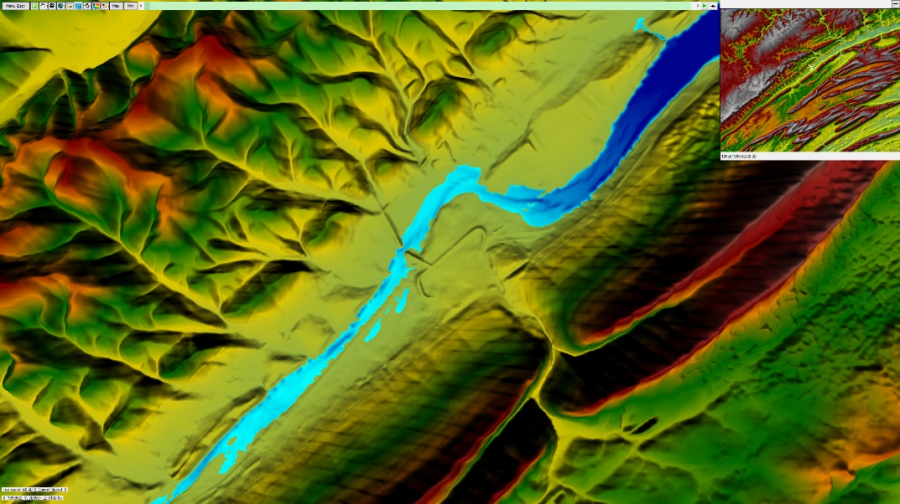
Figure 8 13. 3D Viewer Interface.
Menu and Options
To access the menu to see options, help, and to quit the application, either click on the menu button on the top left corner or press the escape key.
Figure 8 14. 3D Viewer Menu and Options Buttons.
When the Options button is selected a window will appear with four Tabs (General; Graphics; Controls; and Particle Tracing). The following tables describe each of the options on the four Tabs.
General Options
Table 8 1. General Options
| Option | Description |
|---|---|
| Water During Animation | When this option is turned on, the water resolution will be the same resolution as the terrain, based on Level of Detail settings. Animation may play slower than usual with this option turned on |
| Z Scale | How much the terrain elevation is scaled by. Higher value exaggerates the elevations of the terrain, making it easier to see subtle changes in terrain. |
Graphics
Table 8 2. Graphics Options
| Option | Description |
|---|---|
| Aspect Ratio | The aspect ratio of the desired resolution. Most monitors are 16:9 aspect ratio. Changing the aspect ratio will change the available resolutions. |
| Resolution | The resolution of rendering in 3D. Higher resolution means more detail. Can only set resolution to resolutions available for your monitor. |
| Level of Detail | Controls the distance at which lower resolution 3D models are used Higher level of detail means more distance before lower resolution 3D models are used. |
| Shading Mode | Controls how shading is done. Sharp shading will create a more accurate representation of shading, at a cost of performance. Smooth shading is less accurate but more performant |
Controls
There are three ways to control the 3D Viewer, mouse and keyboard, just mouse, and a game controller. These controls options controls certain aspects of using the mouse, keyboard, and game controller.
Table 8 3. Controls for mouse and controller sensitivity.
Option | Description |
Mouse Sensitivity | Controls how much the view changes with mouse movement. Higher sensitivity means more view change with mouse movement. Default is 0.1 |
Controller X Sensitivity | Control how much the view changes with the right stick of the game controller, horizontal axis only. Default is 0.3 |
Controller Y Sensitivity | Control how much the view changes with the right stick of the game controller, vertical axis only. Default is 0.15 |
Invert Y Axis | When this is turned on, moving the vertical axis on either the mouse or game controller will change the view in the opposite direction. Default is off |
Pressing the Change Key/Controller bindings button will bring up a different window where you can change the various bindings for all the controls of the 3D Viewer.
Table 8 4. Controls for Moving around within the 3D Viewer.
Action | Default Key Binding | Default Controller Binding | Description |
| Move Forward | W | Left Stick up | Moves the viewer forward in space |
| Move Backward | S | Left Stick down | Moves the viewer backward in space |
| Strafe Left | A | Left Stick Left | Moves the viewer in a left side-step fashion in space |
| Strafe Right | D | Left Stick Right | Moves the viewer in a right side-step fashion in space |
| Increase Elevation | Space | Right Shoulder Button | Moves the viewer up in space |
| Decrease Elevation | Left Control | Left Shoulder Button | Moves the viewer down in space |
Change Results Map | M | North Button (Y on Xbox, Triangle on PS) | Changes the results map between 4 different maps, a realistic map, depth map, velocity map, and water surface elevation map |
| Toggle Particles | P | West Button (X on Xbox, Square on PS) | Turns on or off the particle tracing effect |
| Flight Path Play/Pause | Return (Enter) | East Button (B on Xbox, Circle on PS) | While a flight path is active, will either play the path or pause it. |
| Increase Viewer Speed | Right Arrow | Right Directional Arrow | Makes the viewer travel faster. The viewer can only go so fast however. |
| Decrease Viewer Speed | Left Arrow | Left Directional Arrow | Makes the viewer travel faster. The viewer can only go so slow however. |
| Turn Left | Unbound | Right Stick Left | Rotates the view to the left |
| Turn Right | Unbound | Right Stick Right | Rotates the view to the right |
| Profile Increment Increase | Up Arrow | Up Directional Arrow | While the animation is playing, the number next to the play button shows how many profiles advance every time the scroll bar scrolls. This increases that number. |
| Profile Increment Decrease | Down Arrow | Down Directional Arrow | While the animation is playing, the number next to the play button shows how many profiles advance every time the scroll bar scrolls. This decreases that number. |
| Change View Up | Unbound | Right Stick Up | Rotates the view up (No changeable binding yet) |
| Change View Down | Unbound | Right Stick Down | Rotates the view down (No changeable binding yet) |
| Toggle Mouse Pointer | Tab | Left Trigger Button | Will either show or hide the mouse pointer (No changeable binding yet) |

Figure 8 15. Spatial representation of action bindings for an Xbox controller.
Particle Tracing
Table 8 5. Controls for Controlling Particle Tracing.
Option | Description |
Speed | Refers to the animation speed of the particle trace. Default value is 1. |
Density | Refers to concentration of tracers in an area. Default value is 1. |
Width | Refers to the width of the particle. Default value is 5. |
Lifetime | Refers to how long the particle exists on screen before it disappears and a new particle spawns in its place. Default value is 300. |
| #Particles | Refers to how many particles are shown at any one time. Default value is 10,000. |
RGB | Changes the color of the tracers. Each field accepts an integer between 0 and 255. R corresponds to Red, G corresponds to Green and B corresponds to Blue |
Toolbar
![]()
The Toolbar is located at the top left of the 3D Viewer window. The following Table describes each of the tools.
Table 8 6. Description of each of the 3D Viewer Tools located on the Toolbar.
Tool | Description | |
Select |
| Wherever the select pointer is at, it will show the value of either the terrain elevation or water surface value, dependent on the map type chosen. |
Pan |
| Left click with the pan pointer to navigate through the terrain by clicking and dragging the terrain. |
Change Camera Modes |
| Allows you to change how the 3D Viewer is controlled. |
Zoom to Entire Extent |
| Zooms to the maximum viewable extent of the terrain, and forces the viewer to look straight down. |
Measure Tool |
| Measure the distance in map units. (Not Implemented Yet) |
Toggle Particle Tracing |
| Toggles whether particles show on the water surface. |
Particle Tracing Options |
| A shortcut to get to Particle Tracing Options |
Change Results Map |
| Changes the results map between 4 different maps, a realistic map, depth map, velocity map, and water surface elevation map |
Select a Flight Plan |
| Opens the flight plan window to choose a flight plan. See Flight Plans/Paths section for more information. |
Set to Simulation Maximum | Max | Sets the water surface to simulation maximum. |
Set to Simulation Minimum | Min | Sets the water surface to simulation minimum. |
Animation Bar |
| Change the animation bar position to change the time of the simulation. When a portion of the animation bar is grey, it means that the simulation has not loaded at that time yet. |
Play/Pause |
| Plays or pauses the animation |
| Profile Increment | +1, +2, +3, +5, +10, +25, +50, +100 | This number indicates how many profiles advance every time the scroll bar scrolls. This will also start loading portions of the simulation that fall on the increments. |
Change Animation Speed |
| Changes the delay before changing time step in the animation. Note that there is an inherent delay that is unavoidable for each time step. That delay depends on whether you pre-processed the dataset, |
Min map
The mini map is shown to assist with acquiring bearings when using the 3D Viewer. Shown in the Figure below is an example of the mini map, which is displayed in the upper right hand corner of the 3D Viewer.
Figure 8 16. Example of the 3D Viewer Mini Map.
There are three components to the mini map, which are explained in the Table below.
Table 8 7. Components of the 3D Viewer Mini Map.
Component | Description |
Hide/Show Button | On the top right of the mini-map is a button that will hide or show the mini-map. |
Mini-map | A character on the mini-map |
Simulation Date/Time | Shows the current Date/Time for the simulation |
Speed/Position Information
On the bottom left corner of the viewer is information about the viewer's speed and its position. A description of these components is in the Table below.![]()
Table 8 8. Speed and Location Components.
Component | Description |
Top Speed | The maximum speed that the viewer can currently travel. Can be increased/decreased with the Increase/Decrease Viewer Speed key bindings. |
Current Speed | While the viewer is moving, the current speed will update to show the viewer's current speed. |
X,Y | The position of the viewer on the XY plane. These coordinates are the same ones used in RAS Mapper |
Z | The elevation of the viewer |
Notes on Large Terrains/Dense Models
The 3D viewer currently works better for dense terrains that are are on the smaller side. The initial loading process (the splash screen) has to create a node for every terrain tile in the terrain model, so if the terrain is expansive and it has high resolution data, it may take a little bit of time before the 3D Viewer can load. The 3D Viewer's current Level of Detail implementation also works better for less expansive terrains. There are tools for cutting terrains to either a certain view extent, or the extent of the geometry. It is possible you may have to cut small sections and view the various sections separately. See Exporting RAS Terrains