Download PDF
Download page Working with Projects.
Working with Projects
To create a river hydraulics application with HEC-RAS, you work with projects. A project is a collection of files that are used to build a model. This section describes projects and how you build and manage the project files.
Understanding Projects
As you develop an application, the management of all the files that get created is accomplished through the user interface. When a new project is started, the user is requested to enter a title and filename for the project. All other data are automatically stored by the user interface using the same name as the project file (e.g. filename.prj), except for the three character extension. A project consists of:
- One Project file (.PRJ)
- One file for each Plan (.P01 to .P99)
- One corresponding HDF5 output file for each Plan (.P01.hdf to .P99.hdf)
- One Run file for each steady flow plan (.R01 to .R99)
- One Run file for each unsteady flow plan (.X01 to .X99)
- One Output file for each plan (.O01 to .O99)
- One file for each set of Geometry data (.G01 to .G99)
- One corresponding HDF5 file for each geometry file (.g01.hdf)
- One file for each set of Steady Flow data (.F01 to .F99)
- One file for each set of Unsteady Flow data (.U01 to .U99)
- One file for each set of Quasi-Unsteady Flow data (.q01 to .q99)
- One file for each set of Sediment data (.S01 to .S99)
- One file for each set of Hydraulic Design data (.H01 to .H99)
- One RAS Mapper file if you are using spatial terrain data (.rasmap)
- One file for each set of Sediment Transport Capacity data (.SedCap01 to .SedCap99)
- One file for each set of SIAM Input Data (.H01.SiamInput to .H99.SiamInput)
- One file for each set of SIAM Output (.H01.SiamOutput to .H99.SiamOutput)
- One file for each set of Water Quality data (.W01 to .W99)
- One Log file per project (.log)
- One text file for each plan executed, containing the computational messages that come out on the computation window (.comp_msgs.txt)
After unsteady flow computations are performed, some additional files will get created during the computations that are only used by the software as intermediate files. These files are:
- One Boundary condition file for each plan executed (.b01 to .b99)
- One unsteady flow Log output file for project (.bco)
- One geometric pre-processor output file for each set of Geometry data (.c01 to .c99)
- One detailed computational level output file for each plan, if user turns this option on (.hyd01 to .hyd99)
- One initial conditions file for each unsteady flow plan executed (.IC.O01 to .IC.O99)
- One binary log file for each plan executed. Used only by the user interface (.p01.blf to .p99.blf)
- One restart file (Hot start) for each unsteady flow plan. This will only show up if the user turns on the option to write it (.p01.rst to .p99.rst)
- One HDF5 binary Output file for each plan that gets executed (.p01.hdf to .p99.hdf). This is the file that RAS Mapper uses for getting HEC-RAS computed results to then visualize as inundation maps and other spatial data displays.
After sediment transport computations are performed, some additional files will get created during the computations that are only used by the software as intermediate files. These files are:
- One detailed sediment output file for each plan (.sed01 to .sed99)
- One header file for the cross section output for each plan (.SedHeadXS01 to . SedHeadXS99)
- One cross section output file for each plan (.SedXS01 to .SedXS99)
After water quality computations are performed, some additional files will get created during the computations that are only used by the software as intermediate files. These files are:
- One water quality log file per plan executed (.bc01 to .bc99)
- One water quality restart file per plan executed (.p01.wqrst to .p99.wqrst)
- One water quality color scale file for each project (.color_scales)
The Project File contains: the title of the project; the units system of the project; a list of all the files that are associated with the project; and a list of default variables that can be set from the interface. Also included in the project file is a reference to the last plan that the user was working with. This information is updated every time you save the project.
Elements of a Project
The following sections describe the various types of files that can be included in a project. All of these files are either created by the user interface or the various computation engines. The modeler interacts with the data through the user interface, and is not required to create or edit any of these files directly.
Plan Files
Plan files have the extension .P01 to .P99. The "P" indicates a Plan file, while the number represents the plan number. As plans are created, they are numbered from 01 to 99. The plan file contains: a description and short identifier for the plan; a list of files that are associated with the plan (e.g., geometry file and steady flow file); and a description of all the simulation options that were set for the plan. The plan file is created automatically by the interface each time the user selects New Plan or Save Plan As from the simulation windows.
Run Files
Run files have the extension .R01 to .R99. The "R" indicates a Run file, while the number represents an association to a particular plan file. A file with an extension of .R01 is the run file that corresponds to the plan file with the extension .P01. The run file contains all of the necessary data to perform the computations that are requested by the associated plan file. For example, if a steady flow analysis is requested, the run file will contain geometry data, steady flow data, and all the necessary computational options that are associated with the plan file. The run file contains the input to any of the computational engines available in the HEC-RAS system. The run file is automatically generated by the interface whenever the user presses the Compute button on the Simulation windows. The run file is in an ASCII format, but it is not self explanatory.
Output Files
Output files have the extension .O01 to .O99. The "O" indicates an Output file, while the number represents an association to a particular plan file. A file with the extension .O12 is the output file that corresponds to the plan file with an extension .P12. The output file contains all of the computed results from the requested computational engine. For example, if a steady flow analysis is requested, the output file will contain results from the steady flow computational engine. The output files are in a binary file format and can only be read from the user interface.
In addition to the standard output file, there is also an HDF5 output file that corresponds to each Plan. This output file is used to support HEC-RAS Mapper. All of the output shown in HEC-RAS Mapper comes from this HDF5 output file.
Geometry Files
Geometry files have the extension .G01 to .G99. The "G" indicates a Geometry file, while the number corresponds to the order in which they were saved for that particular project. Geometry files contain all of the geometric data for the river system being analyzed. The geometric data consist of: cross section information; hydraulic structures data (e.g., bridges and culverts); coefficients; and modeling approach information. The geometry data are stored in an ASCII format. The file contains key words to describe each piece of data, and is for-the-most-part self explanatory. A geometry file is created by the user interface whenever the modeler selects New Geometry Data or Save Geometry Data As from the Geometric Data window. Each Geometry file has a corresponding HDF5 Geometry file that is used in when editing and visualizing in HEC-RAS Mapper, and used for computation purposes.
Steady Flow Data Files
Steady flow data files have the extension .F01 to .F99. The "F" represents that it is a steady Flow data file, while the number corresponds to the order in which they were saved for that particular project. Steady flow data files contain: the number of profiles to be computed; flow data; and boundary conditions for each reach. The steady flow data files are stored in an ASCII format. The file contains key words to describe each piece of data, and is for-the-most-part self explanatory. Steady flow data files are automatically created by the user interface when the modeler selects New Flow Data or Save Flow Data As from the Steady Flow Data window.
Unsteady Flow Data Files
Unsteady flow data files have the extension .U01 to .U99. The "U" represents that it is an unsteady flow data file, while the number corresponds to the order in which they were saved for that particular project. Unsteady flow data files contain: flow hydrographs at the upstream boundaries; starting flow conditions; and downstream boundary conditions. The unsteady flow data files are stored in an ASCII format. The file contains key words to describe each piece of data, and is for-the-most-part self explanatory. Unsteady flow data files are automatically created by the user interface when the modeler selects New Flow Data or Save Flow Data As from the Unsteady Flow Data window.
Quasi-Unsteady Flow Data Files
Quasi-Unsteady flow data files have the extension .Q01 to .Q99. The "Q" represents that it is a quasi-unsteady flow data file, while the number corresponds to the order in which they were saved for that particular project. Quasi-Unsteady flow data files contain: flow hydrographs at the upstream boundaries; starting flow conditions; and downstream boundary conditions. The quasi-unsteady flow data files are stored in an ASCII format. The file contains key words to describe each piece of data, and is for-the-most-part self explanatory. Quasi-Unsteady flow data files are automatically created by the user interface when the modeler selects New Flow Data or Save Flow Data As from the Quasi-Unsteady Flow Data window.
Sediment Data Files
Sediment data files have the extension .S01 to .S99. The "S" represents that it is a Sediment data file, while the number corresponds to the order in which they were saved for that particular project. Sediment data files contain: flow data; boundary conditions for each reach; and sediment data. The sediment data files are stored in an ASCII format. The file contains key words to describe each piece of data, and is for-the-most-part self explanatory. Sediment data files are automatically created by the user interface when the modeler selects New Sediment Data or Save Sediment Data As from the Sediment Data editor.
Water Quality Data Files
Water Quality data files have the extension .w01 to .w99. The "w" in the extension marks these files as water quality data files, while the number corresponds to the order in which they were saved for that particular project. Water Quality data files contain: temperature boundary conditions for each reach, initial conditions, advection dispersion parameters and meteorological data. The data files are stored in an ASCII format. The file contains key words to describe each piece of data, and is for-the-most-part self explanatory. Water quality data files are automatically created by the user interface when the modeler selects New Water Quality Data or Save Water Quality Data As from the Water Quality Data window.
Hydraulic Design Data Files
Hydraulic design data files have the extension .H01 to .H99. The "H" represents that it is a Hydraulic design data file, while the number corresponds to the order in which they were saved for that particular project. Hydraulic design data files contain information corresponding to the type of hydraulic design calculation that is requested. The Hydraulic design data files are stored in an ASCII format. The file contains key words to describe each piece of data, and is for-the most-part self explanatory. Hydraulic Design data files are automatically created by the user interface when the modeler selects New Hydraulic Design Data or Save Hydraulic Design Data As from the File menu of the Hydraulic Design Functions window.
A schematic diagram of how the data files fit together is shown in the figure below. In this example there are three plans in the project. Each plan represents a specific set of steady flow data and geometry data. In this example there are three geometry files and one steady flow file. The first geometry file could represent the existing conditions of the stream. The second and third geometry file could represent some modification of that base geometry file, such as adding a bridge or culvert crossing; a channel modification; different roughness coefficients; or any other change to the base geometry file. A plan is formulated by selecting a steady flow file and a geometry file, and then saving that plan with a specific title and short identifier. For more information about formulating plans, see Chapter 7 of the HEC-RAS User’s Manual and Chapter 7 of the HEC-RAS Applications Guide.
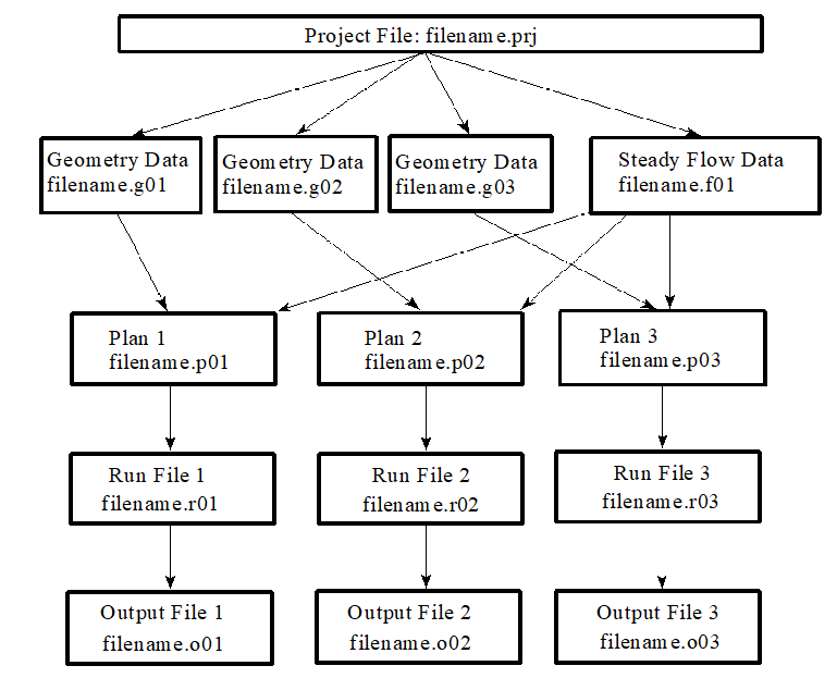
Schematic of Project Data Files
Creating, Opening, Saving, Renaming, and Deleting Projects
The following commands from the File menu of the HEC-RAS main window allow you to create, open, save, rename, and delete projects. These commands are the same for all of the other data types that get created by the user interface (Plan data, geometry data, steady flow data, unsteady flow data, sediment data, and hydraulic design data).
| File Menu Command | Description |
|---|---|
| New Project | Closes the current project, prompting you to save the data if anything has been changed. The user is then prompted to enter a title and filename for the new project. |
| Open Project | Closes the current project, prompting you to save the data if anything has been changed. Opens an existing project and all of the associated files. |
| Save Project | Updates the project file and all other files in which data have been modified. |
| Save Project As | Updates the project file and all other associated data, saving all the information to a new filename that you specify. |
| Rename Project | Allows the user to rename the title of the currently opened project. |
| Delete Project | Deletes the project file and all other files associated with the selected project. The user is prompted to make sure that they really want to delete all of the files. |
| Project Summary | Displays a summary of the project, including: directory locations; project plans; a list of the files contained in the project; and currently opened Plan Statistics (i.e. number of various elements). |
Project Options
From the Options menu of the main HEC-RAS window, the user can set several default project options. These options include: program setup options; setting default hydraulic variables; establishing the default units system (English or Metric); and converting existing projects to a different units system (English to Metric or Metric to English). The following four options (and sub-options) are available from the Options menu:
Program Setup
- Default File Viewer: This option allows the user to change which program is used for viewing the report generator and log file output. The default is the Windows Write program. The user can change this to any file viewer on their system.
- Default Project Folder: This option allows the user to set the default directory in which they want HEC-RAS to look for data files. When starting a new project, or opening an existing one, the HEC-RAS file chooser has a button to automatically switch the current directory to whatever the user has set for the “Default Project Folder.”
- Open last project: When this option is selected, the program will automatically open the last project worked on, during startup.
- Automatically backup data: When this option is checked, the program will automatically make a backup of the currently opened project, plan, geometry, and flow files. The backup files are updated at specific timed intervals, which is user controlled. The backup files are stored in the \HEC\RAS directory, with the titles RasBackup.prj, RasBackup.p01, RasBackup.g01, and as Backup.f01.
- Set time for backup: This option allows the user to control the automatic time interval between updating the backup files. The default value is 20 minutes.
- Use 64-bit computation engines (when available): When this option is selected, the software will use the 64 bit versions of the computational engines, rather than the 32 bit versions. The operating system must be a 64 bit operating system for this to work. In general, the 64 bit versions of the software will run faster than the 32 bit. Additionally, the 64 bit versions of the software can access all of the RAM memory available on the machine, which allows user to work on larger models that require more memory space.
Default Parameters: This option allows the user to set defaults for some of the hydraulic variables.
Unit System: This option allows the user to set the default units system to either English or Metric. Once the units system is set, the program assumes that all input data are entered in that units system. Likewise, the display of all output data will be done in the default units system.
Convert Project Units: This option allows the user to convert an existing project from one units system to another. Projects can be converted from English to Metric or from Metric to English.
Convert Horizontal Coordinate System: This option allows the user to convert the Horizontal coordinate system used in the project, to another horizontal coordinate system.