Download PDF
Download page 2D Flow Areas.
2D Flow Areas
The 2D Flow Areas Group contains features that are used to create the 2D Flow Area computational mesh: perimeters, computation points, breaklines, and refinement regions. This layer is not editable. A 2D flow area is developed by first adding a new Perimeter. Then the user can create a mesh by bringing up the 2D Flow Area Editor, entering a base point spacing (DX and DY), and then generating cell points. After a base set of cell points are generated for a 2D Flow Area, users can refine the mesh by adding additional points, Breaklines, and Refinement Regions. When creating the 2D Mesh, the order in which RAS computes the mesh is to: (1) use the points from the computation points layer; (2) insert the refinement region points and perimeter as breaklines; (3) insert the breakline points (overriding points within a buffered area around the breakline); (4) triangulate the computation points; and (5) develop the computational mesh from the triangulation.
Perimeters
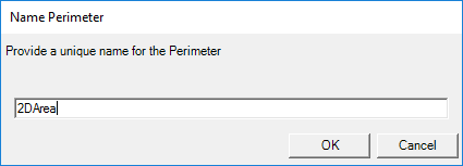
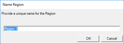
The Perimeters layer is used to define the polygon boundary for a 2D Flow Area. Upon completion of drawing a boundary polygon, the user will be prompted to name the 2D Flow Area, as shown below.
The 2D Flow Area editor, shown below, is then accessed either by right-clicking on the 2D Flow Area feature or right-clicking on the Perimeters layer and selecting the Edit 2D Area Properties menu item.
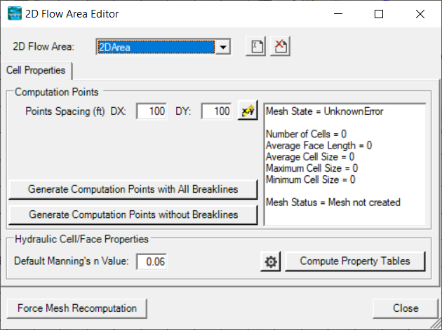
The computational mesh is created based on computation points. Enter the nominal cell center Points Spacing, and press either Generate Computational Points button. This will create computational mesh based on an evenly distributed “grid” of points and generate cells that have faces orthogonal to the connections of each computation point. The Generate Computational Points with All Breaklines button will create the computation points using any Breaklines or 2D Structures that are defined in the Geometry. The Generate Computational Points without Breaklines button will create the computation points ignoring the presence of any Breaklines or 2D Structures defined in the Geometry.
After computing the mesh, the mesh status window will provide information of the success of the mesh generation and some statistics, such as the number of cells in the mesh. The computation points that were used to generate the mesh are stored in the Computation Points layer.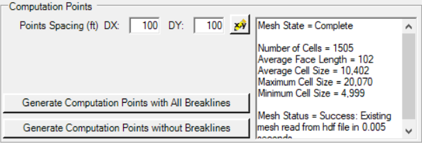
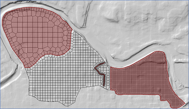
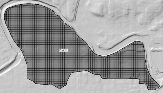
The computational mesh will be drawn to the Map Window. The visualization of the mesh is controlled by the 2D Flow Areas group (not by the Perimeters layer, which only controls the boundary).
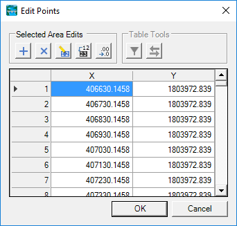
The 2D Flow Area Editor also provides access the points used to generate the computational mesh, by pressing the  Edit/View Points button. The computation points, however, are visualized by the Computation Points layer, discussed below. The Edit Points table is available many places in RAS Mapper and allows the user to Add, Multiply, Set, Replace, and Adjust decimal places for values within the selected area of the table. Users can also cut, copy, and paste points from and into this editor.
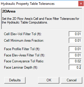
The 2D Flow Area Editor also provides access to a Default (base) Manning’s n value for all cells in the 2D Area and Filter Tolerances for the computation of the Hydraulic Property Tables (shown below).
Computation Points
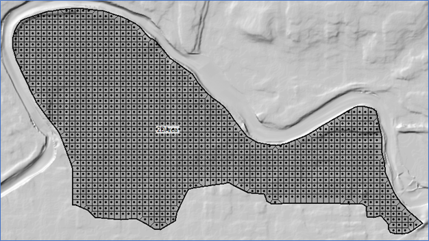
Points used to generate the 2D Flow Area meshes are stored on the Computation Points layer. All points for all of the 2D Flow Areas are stored in one multipoint feature in the Computation Points layer. Because there may be many, many mesh points, when in edit mode, the Computation Points layer must be the Edit Layer for the points to be drawn. Further, you must be zoomed in such that there are less than 15,000 points within the view area, for the points to be displayed. An example mesh with points displayed is shown below.
As points are modified in the Computation Points layer, the visible portion of the mesh (with a surrounding buffer) will be recomputed on-the-fly. This will allow the user to see the impacts of modifying a point. An illustration of moving a point and mesh re-computation is shown below.
Breaklines
Breaklines are a hydraulic modeler’s best friend (second only to a faithful four-pawed companion). The Breaklines layer is a set of polylines used to enforce cell faces along linear features, such as high ground, to direct the movement of water through the 2D domain. Typically, you can start with a coarse 2D mesh and then begin refining and improving the mesh with the use of breaklines.
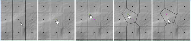
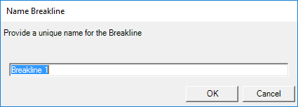
To add a breakline, draw a polyline where you’d like the cell faces to be aligned. When finished creating a breakline, you will be prompted to provide a name for the breakline.
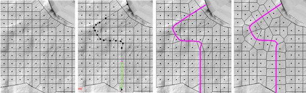
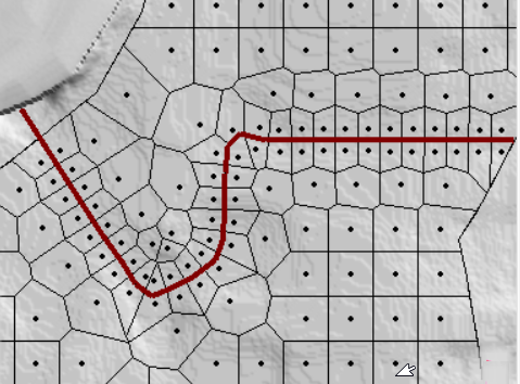
Also, after finishing a breakline, the local mesh will update to show how cell faces have magnetized to the breakline. To enforce the breakline, right-click on the breakline feature and choose the Enforce Breakline menu item. Enforcing a breakline will clear out any cell points on either side of the line based on the 2D Flow Area cell point spacing value (default behavior). New points will then be added on either side of the line to produce cells at (approximately) the default cell point spacing. An example of breakline insertion and enforcement is show in the figure below.
Once a breakline has been created, you can right-click on it for specific options to edit properties, enforce, and rename the breakline.
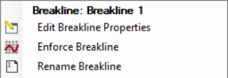
The breakline insertion algorithm is a complicated process: points near to the line are removed and then points are added to the mesh in attempt to align the cell faces with the breakline. By default, the cell point spacing for the 2D Flow Area is used to determine how often points are inserted. However, the breakline properties offers a much more robust option for removal of existing points and insertion of new points. The Breakline Editor, available by right-click on the feature or the Breakline layer and selecting the Edit Breakline Properties menu item, allows you to modify the properties of each breakline.
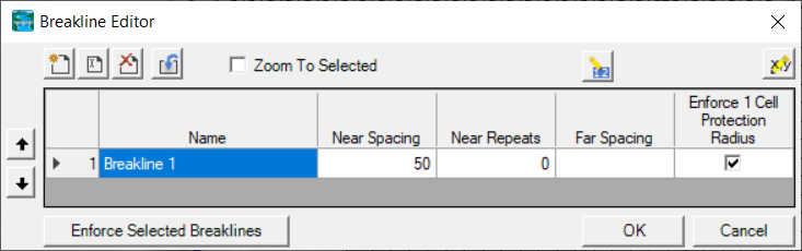
The properties for each breakline include the Name, Near Spacing, Far Spacing, and Near Repeats are summarized below. These properties (other than the Name) control how the breakline will be used to modify the mesh, when enforced.
| Property | Description |
|---|---|
Name | Each breakline must have a unique name. Editor tools are available to |
Near Spacing | The distance to add computation points along the breakline (i.e. how often are point added). The points are added next to the line at ½ the near spacing value. If not specified, the default value is the point spacing on the 2D Flow Area. |
Far Spacing | How large a distance to go, when adding points, away from the line. Computation points will be added sequentially starting with the Near Spacing and transition (doubling the previous spacing) out until the Far Spacing values is achieved (approximately). If not specified, the default value is the point spacing on the 2D Flow Area. |
Near Repeats | The number of times the Near Spacing will be used before the doubling of previous spacing begins. If not specified, the default value is zero. This property is used in cases where the breakline needs to provide detailed spacing along a feature such as a channel or on top of a hydraulic structure. |
Enforce 1 Cell Protection Radius | A protective region buffered around the breakline that extends by the Near Spacing distance on each side. Within this protection region, computation points can neither be added nor removed by the cell generation routines. This means that any previous hand-edits to those computation points will remain, and any nearby breaklines cannot interfere with this already-enforced region. |


When a breakline is enforced, it is added to the 2D area by first removing the computation points within a certain buffered region. This buffered region is computed from the Near Spacing, Far Spacing, and Near Repeats to make room for points that will be added as the spacing transitions from the Near Spacing to the Far Spacing values. As points are added back into the mesh along the breakline, the points are added such that the point spacing will double the cell size for each set of new cells that are added laterally away from the breakline. An example of a breakline based is shown below.
Refinement Regions
Refinement regions are used to change the cell point spacing for specific areas within a 2D Flow Area. A polygon is created to define the boundary of the refinement region. The interior of the area is given a cell spacing (just like the Perimeter layer) and the bounding polyline is given a point spacing (just like a breakline). Refinement regions can be used to increase the computation point density in an area where you would like more detailed results due to rapid changes in terrain or water surface elevation or to simplify an area where the water surface elevation will not vary much and you want to reduce the number of computation points in the 2D Flow Area. After creating a refinement region polygon, you will be prompted to name the feature.
Additional properties for controlling how the regions affects the 2D Flow Area are accessed through the Refinement Region Editor. The Refinement Region Editor, available by right-click on the feature or the Refinement Region layer and selecting the Edit Refinement Region Properties menu item, allows you to modify the properties of each region. When a refinement polygon is enforced, the boundary is treated much like a breakline where the point spacing along the breakline grows larger the farther you get away from the line. This transition of cell sizes happens both outside of the boundary and on the inside of the polygon.
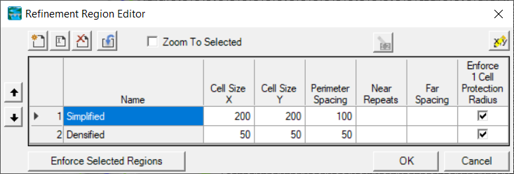
The properties for each refinement area include the Name, Cell Spacing X, Cell Spacing Y, Near Spacing, Far Spacing, and Near Repeats. These properties control how the refinement region will be used to modify the mesh, when enforced.
| Property | Description |
|---|---|
Name | Each region must have a unique name. |
Cell Spacing X | The spacing distance in the X-direction for adding computation points inside of the refinement region. |
Cell Spacing Y | [NOT IMPLEMENTED YET] The spacing distance in the Y-direction for adding computation points inside of the refinement region. |
Perimeter Spacing | The distance to add computation points along the region boundary (i.e. how often points are added) just as done with the Near Spacing on the Breakline layer. The points are generally placed along the line offset by ½ of the spacing value. If not specified, the default value is the Cell Spacing X value. |
Far Spacing | How large the max cell will be to go when computation points away from the line. Computation points will be added sequentially starting with the Near Spacing and doubling the previous spacing until the Far Spacing values is achieved (approximately). If not specified, the default value is the point spacing on the 2D Flow Area. |
Near Repeats | The number of times to duplicate the Perimeter Spacing on both sides of the polygon boundary before transitioning to the Far Spacing. If not specified, the default value is zero. |
Enforce 1 Cell Protection Radius | A protective region buffered around the perimeter that extends by the Perimeter Spacing distance on each side. Within this protection region, computation points can neither be added nor removed by the cell generation routines. This means that any previous hand-edits to those computation points will remain, and any nearby breaklines cannot interfere with this already-enforced region. |