Download PDF
Download page Terrain Layer.
Terrain Layer
The first step in creating a good hydraulic model is having good terrain data. A good terrain model represents the ground surface well in locations that affect the movement of water through the floodplain. HEC-RAS supports the use of terrain data in a raster format - once terrain data has been imported to HEC-RAS it is referred to as a RAS Terrain.
HEC-RAS supports the use of a digital terrain model (DTM) for representing the bare earth ground surface. The RAS Terrain support is for raster data of many formats, but once processed, the data will be stored in the GeoTiff format. In order to properly represent the floodplain area and develop an accurate geometry for the river analysis, the DTM must have representative data in the main channel and the overbank areas. In other words, a good terrain model is comprised with accurate bathymetric information to supplement the more readily acquired overbank information. The definition of linear features that direct the movement of water such as levees, floodwalls, and roadways should be captured in the terrain model while such features as bridges should not be included. Further, if a detailed 2D model is being developed, bridge piers, training walls, and buildings should be included in the terrain such that they can eventually be included in the 2D Flow Area mesh.
Because RAS supports a DTM as a gridded model, the grid-cell size used to represent the terrain must be small enough that it captures the features of the terrain. For instance, even though a larger cell size may appropriately capture the ground surface definition in the overbank areas, the cell size must be small enough to capture the more abrupt changes in elevation that tend to occur in the main channel. If the model is intended to capture the detailed hydrodynamics through a bridge opening, the grid-cell size must be small enough to capture and represent the piers (or high ground) that will significantly direct flow. When used for developing 2D Flow Area information, RAS will allow the placement of breakline locations (to align cell faces) where elevation data will be extracted for cell faces elevation profiles. In the event that sufficient detail is not provided in the terrain model (such as at a levee), the hydraulic structure option is available in RAS to override elevation data.
Terrain data can be used in RAS to visualize the floodplain geometry. It is also used for preprocessing geometric data for 2D Flow Areas, computing flood depths, and inundation boundaries from simulation results. To use a Terrain Layer in RAS Mapper it must first be “created” and then “associated” with the geometry and plans of interest.
RAS Terrain Development
A new Terrain Layer is created by selecting one or many raster (gridded) datasets and importing them into a single layer. This is done through the New Terrain Layer dialog, shown the figure below. Each raster is added to the dialog and the user is encouraged to establish each raster’s priority when being used for computations (higher priority data are listed above lower priority data). A filename and location is then provided for the Terrain Layer and the precision with which data will be rounded is specified.
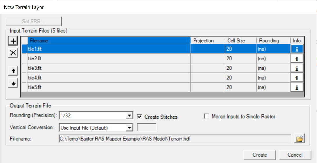
Input Terrain Files are added to the dialog through the ![]() Add Files button. These are the files that will be imported and evaluated by the priority defined in the list. The terrain file at the top of the list has the highest priority when evaluating the Terrain Layer. Each file will be evaluated and stored as a GeoTiff in the Terrain Folder with the name “Terrain Name.Filename.tif”. RAS Mapper supports numerous raster file types through its use of the GDAL libraries including the binary raster floating point format (.flt), esri grid (.adf), and GeoTiff (.tif). (A full list of raster format supported by GDAL can be found here: http://www.gdal.org/formats_list.html). Terrain priority can be established using the
Add Files button. These are the files that will be imported and evaluated by the priority defined in the list. The terrain file at the top of the list has the highest priority when evaluating the Terrain Layer. Each file will be evaluated and stored as a GeoTiff in the Terrain Folder with the name “Terrain Name.Filename.tif”. RAS Mapper supports numerous raster file types through its use of the GDAL libraries including the binary raster floating point format (.flt), esri grid (.adf), and GeoTiff (.tif). (A full list of raster format supported by GDAL can be found here: http://www.gdal.org/formats_list.html). Terrain priority can be established using the ![]() Move Up and
Move Up and ![]() Move Down buttons. A terrain model can be removed using the
Move Down buttons. A terrain model can be removed using the ![]() Delete button.
Delete button.
Rounding specifies the precision with which the new raster data are stored. Rounding the terrain data allows for more efficient compression of data, resulting in smaller files sizes on disk and faster processing times within RAS Mapper for inundation analysis. The default value of 1/32 of a map unit was found to be the best trade-off between file size and precision because rounding to base-2 values is more efficient for file compression than base-10 values. (Rounding to 1/32 means that each data point created in the GeoTiff will be +/- 0.015625 of the raw data value.)
Vertical Conversion can be performed as the terrain input files are imported. The default method attempts to ready the input file and determine whether conversion should take place. If you KNOW what should happen, select the options from the pick list (Feet to Meters, Meters to Feet, Custom Value, or No Conversion).
Create Stitches automatically creates a triangulation surface between imported terrain models. This will create a continuous surface and fill in holes in the terrain surface for elevation extraction along cross sections and 2D cell faces.
Merge Inputs to Single Raster allows you to bring in multiple tiles that are of the same cell resolution and which area all registered and edge-matched to create a single, continuous surface. This option is inteneded be used for bringing in many, many LiDAR tiles that all line up. If you would like one single Terrain model with a single raster cell size, use the Export option on the RAS Terrain after you have imported the data initially.
Filename is used to set the name of the Terrain Layer shown in RAS Mapper – “Terrain” is the default name. A HDF file will be created that has information on what raster data are part of the Terrain Layer as well as information for merging information from adjacent rasters. A second file with the VRT extension will be created. The VRT file is a visualization file allows for displaying multiple rasters at once using the same symbology with just the one VRT file in a GIS.
Steps in Creating a Terrain Layer
The process of creating a new Terrain Layer in RAS Mapper can be a time-consuming process depending on the size and number of raster files to be imported. The steps performed in creating the Terrain Layer are enumerated.
- Converted to GeoTiff - The first step of the Terrain Layer creation process copies and converts the raster data to a new file in the GeoTiff format.
- Projected – If necessary, the raster data is projected from its current coordinate system to the coordinate system specified in RAS Mapper. If a coordinate system is not specified, no projection will take place.
- Tiled – The raster file is stored in data “chunks” that are 256 rows by 256 columns. This helps minimize data access time to improve performance.
- Rounded – Each value in the terrain GeoTiff is rounded to the specified precision. Rounding the data allows for more efficient compression of redundant data files thereby allow for smaller file sizes and faster read/write times. The default value of 1/32 means that all values in the final GeoTiff will be within 1/64 (~0.016) of the original (raw) data value.
- Statistics Generated – Statistics are pre-computed to identify minimum and maximum values to help establish layer processing and symbology.
- Pyramided – The GeoTiff file stores several copies of the base data at lower resolutions to provide an overview of the data at various map scales (zoom levels). This allows for fast display of raster data regardless of the zoom level. Further, on-the-fly computation and display of flood depths is available within RAS Mapper.
Steps 1 – 4 are performed for each file specified in the New Terrain Layer dialog. A separate GeoTiff will be created for each user-specified raster. - VRT – An Xml file is generated (“Terrain.vrt” is default) for display of the newly processed GeoTiff files in alternative GIS software. (Adding only the VRT file will load all of the GeoTiffs.)
- HDF – An HDF file will be created (“Terrain.hdf” is default) which identifies all the GeoTiff files for the Terrain Layer, the priority in which to use GeoTiff values, and stores a computed surface for transitional area between GeoTiffs. The HDF file is the file that is loaded into RAS Mapper; thereby, allowing the user to manage one layer file for the Terrain.
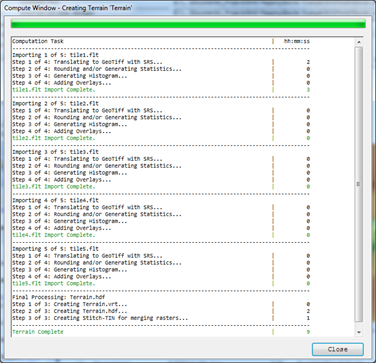
The final GeoTiff files are stored using the base name of the original terrain file prepended by the user-specified terrain name (“Terrain” being the default name). The status of the terrain processing will be reported in the dialog shown in Figure 20‑10. Processing time for each computation task is reported in hours, minutes, and seconds (hh:mm:ss).
There are no intended file size limitations with raster datasets in RAS Mapper. RAS Mapper utilizes the BigTiFF file format which allows for very large file sizes. All GeoTiff files created with RAS Mapper are stored in the BigTiFF file structure.
Terrain Visualization
There are several options for assisting the user in visualizing the Terrain Layer. These options are available by right-clicking on the layer and choosing the Layer Properties option or double-clicking on the layer. Options include the ability to specify Surface Properties, plot contour lines, and use a hillshade effect. The Layer Properties dialog is shown in figure below.
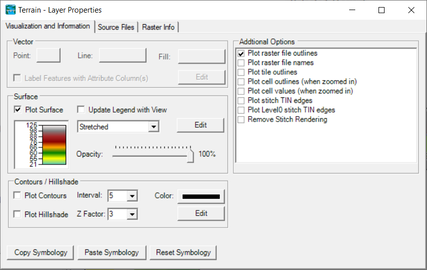
Surface Properties –Surface Properties allow the user to adjust the color ramp used for plotting the terrain. Layer transparency is available using the slider bar left of the color scale. To change the color scale, click on the Edit button. It will bring up the color palette editor and allow the user to change colors palettes, individual colors, and color break values.
Plot Contours – If the Plot Contours option is checked, contour lines will be drawn to the screen based on the specified interval and line symbol color. The contour Interval list has default interval values, however, the user may override the preset values by typing in a value. The contour lines will be generated on-the-fly based on the current view extent and, by extension, the “level” of the terrain data that is shown. If contour plotting is turned on, the contour interval will be appended to the terrain layer name.
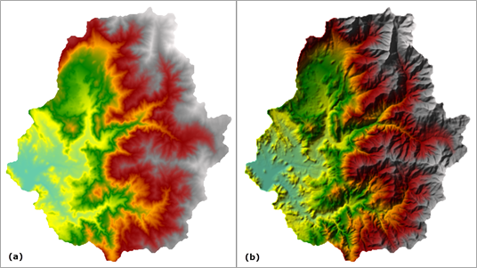
Plot Hillshade – the Plot Hillshade option will render the terrain using a hill shading effect that produces shaded relief based on directing a light source on the terrain which produces shadows in areas obscured from the light. This works to mimic the effect of the sun on the topography, illuminating higher terrain and darkening lower values. The result transforms a flat color ramp into a faux 3-D surface where the relief is clearly visible. The Z-Factor is used to exaggerate the changes in elevation. Changes to the location of the light source can be modified by clicking the Edit button to access the Azimuth and Zenith parameters. An example of the effect of hill shading on terrain is shown in the figure below.
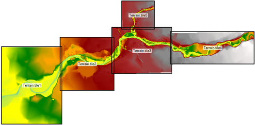
Additional Options – There are several other options for discovering additional information about the Terrain Layer. Options for plotting the Tile File Outlines and File Names are available to get an overview for the extents of the based terrain data. Individual cell values and extents can be plotted when zoomed in to get an idea for the values used in creating the terrain surface. Stitch TIN information can be plotted to show the user how the surface is connected from one terrain tile to another. An example of plotting terrain file extents and name is shown below.
Associating Terrains
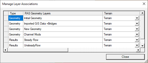
Before you can use a RAS Terrain, you will have to associate it with the Geometry to use it with. Associating a Terrain done by right-clicking on the Terrains group and selecting the Manage Terrain Associations menu option (or Project | Manage Layer Associations menu item). In the dialog that appears, you can select the RAS Terrain for use in extracting information for the geometry or for use when mapping RAS results.
Exporting RAS Terrains
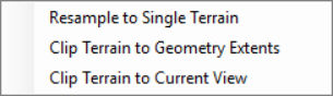
You may wish to change the resolution or geospatial extents of the RAS Terrain model. To create a new RAS Terrain, select the Generate New RAS Terrain menu item and select the process you would like to perform. At this time, you can Resample to a Single Terrain, Clip Terrain to Geometry Extents, and Clip Terrain to the Current View. For each option you will be prompted for additional information with the end result being a new RAS Terrain that is added to the Terrains group.
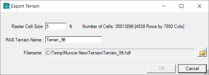
Resample to Single Terrain
The Resample to Single Terrain option will allow the user generate a single RAS Terrain at the specified cell size. The user will also be required to specify the RAS Terrain Name and file location. After the new Terrain is created it will be added to RAS Mapper in the Terrains group.
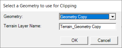
Clip Terrain to Geometry Extents
The option to clip the Terrain to the extents of a Geometry layer is intended to reduce terrain file sizes. After selecting a Geometry and provide a new Terrain Name, press OK. After the new Terrain is created it will be added to RAS Mapper in the Terrains group.
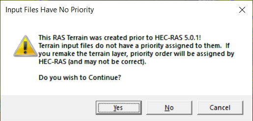
For Terrains that are a composite of multiple terrain tiles, the conversion will check to maintain the previously established tile priority. If the RAS Terrain was created with an older version of HEC-RAS, the priority information may not have been stored in the Terrain file. If the priority cannot be established the user will see an message informing you HEC-RAS isn't sure what to do (shown below). If this is the case, remake the Terrain model and then clip it to the new extent.
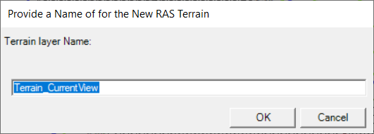
Clip Terrain to Current View
The option to clip the Terrain to the extents of a Geometry layer is intended to reduce terrain file sizes. It works the similar to the clip to geometry option. Provide a new Terrain Name and press OK. After the new Terrain is created it will be added to RAS Mapper in the Terrains group.