The SA/2D Connections layer is used for connections between storage areas and 2D flow areas. It is also used as a hydraulic connection within a 2D Flow Area. A hydraulic structure used within a single 2D Flow Area can be used to simply increase the elevations of the terrain, to specify the equation set to solve for the water surface, or to model a bridge. When creating the hydraulic structure, consider that positive flow (in the downstream direction) is determined based on left to right orientation of the structure. After creating the SA/2D Connection, you will be prompted to provide a Name. Specify a Width for rendering the connection and provide a Description, if desired. You also need to select the Structure Type.
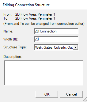
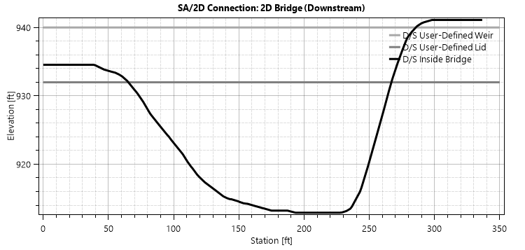
The Structure Type has three possible options: a normal overflow type weir (Weir, Gates, Culverts, ...), Linear Routing, and a Bridge (1D - Family of RCs). All options require the user to complete the hydraulic structure data in the SA/2D Connection editor. If the Bridge option is selected, the Width of the structure will used to place and create Internal Bridge sections (this will be done within the Geometric Data Editor). The Upstream Distance supplied in the SA/2D Connection editor will then place and create Bounding Cross Sections to complete the bridge geometry.
When creating the hydraulic structure inside of a 2D Flow Area, the line will be treated as a breakline where you can specify breakline properties like cell spacing. To access the hydraulic structure's breakline properties choose the Edit 2D Connection Breakline Properties by right-clicking on the SA2/2D Connection layer or an individual 2D Connection.
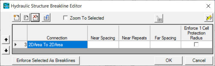
You can enforce the hydraulic structure as a breakline using the Enforce Selected as Breaklines button on then Hydraulic Structure Breakline Editor or by right-clicking on a 2D Connection and choosing Enforce 2D Connection as Breakline.