Download PDF
Download page Terrain Modification.
Terrain Modification
The basis for any accurate river hydraulics model is a good representation of ground surface elevations for the river and floodplain areas. A good terrain model accurately describes the elevations of the river channel and floodplain by incorporating important features that control the movement of water, such as the channel bottom and channel banks, and high ground such as roadways and levees. If the initial terrain model insufficiently represents the ground surface, HEC-RAS provides tools for improving the terrain data directly in RAS Mapper. There are currently two methods for improving channel data in HEC-RAS: (1) using cross sections to create an interpolation surface to add to an existing terrain model; (2) using the vector Terrain Modification tools in RAS Mapper to improve the Terrain by adding channel information, adding high ground (such as a road), adding features that impede flow (such as piers), or otherwise modifying the terrain elevations. RAS Mapper supports many different raster formats; however, the Terrain Modification tools work specifically with the RAS Terrain layer to create a compilation of vector additions to the underlying GeoTiff representation of the grounds surface.
Terrain Modifications can be performed (1) using Cross Sections to create an interpolation surface to export to a raster to be added to a RAS Terrain or (2) using the Terrain Modification Tools to create vector additions to a RAS Terrain.
Cross Section Interpolation Surface
Cross sections can be used to create a ground surface model for use with HEC-RAS. This is often a convenient method for improving a terrain model where a 1D model exists for the channel portion of the land surface. Using the River centeline, cross sections, and bank lines, RAS Mapper can be used to create in interpolated surface of the channel or channel and overbanks. This new surface can then be used to create a new terrain model that combines the channel surface (with top priority) along with the other terrain files. This method can also be used for adding high ground, simply by flipping the cross sections "upside down". The general steps to including elevation information, for specific area of interest (AOI), using cross sections are provided below.
- Create a New Geometry
- Start Editing
- Create River centerline features for the AOI
- Create Cross Sections locations bounding the AOI
- Create Bank Lines layer features to shape and limit the channel influence (if desired)
- Stop Editing
- Modify the cross sections (as desired) in the Geometric Data Editor
- Export the Geometry to a new GeoTiff, providing a cell size for the new raster dataset
- Create a New RAS Terrain using the new channel raster (top priority) and the old terrain models (lower priority) using the Create New RAS Terrain interface

Terrain Modification Tools
Terrain modification tools in RAS Mapper take advantage of the vector editing tools to create points, polylines, and polygons to create vector modifications to an existing RAS Terrain. Terrain modification tools allow the user to add simple shapes with constant elevations (such as rectangles, ellipses, and polygons), complex polylines with multiple elevations and a cross section shape, or complex features such as a polyline or polygon controlled with Elevation Control Points. In order to use the terrain modification capabilities, the Terrain's modification layer must be the Active, Edit Layer. All modifications are performed using the standard vector editing tools.
The modifications have been organized into simple Shapes, complex Lines, and complex Polygons. A summary of the modification group types is provided below.
| Modification | Description |
|---|---|
| Shapes | Shape modifications are defined by an single overriding elevation. Length dimensions vary based on the selected shape type. |
| Lines | Line modifications allow the user to specify elevations along the line to produce an interpolated (3D) line with a shape template for either High Ground or for a Channel. The template and elevations will be interpolated along the profile of the line to create a surface that is merged with the Terrain. A complex Ground Line Editor requires input for the profile line and the ground template. Elevation Control Points can also be used along the modification line to control elevation along the line. |
| Polygons | Polygon modifications allow the user to override an area. The polygon can be a simple rectangle or a multipoint ("free hand") polygon. There are multiple options available to control elevation overrides:
|
Terrain layers are can be very large datasets. Modifications are often experimental and each time a user wishes to change the ground surface elevations, we don't want to make an entire copy of the Terrain. Therefore, terrain modifications have been implemented as vector additions to the Terrain layer. These modifications are stored in the terrain layer's .hdf file. Further, in a continued attempt to reduce data and to keep the base terrain data unmodified, there is an option to create copy of the Terrain data. The Clone Terrain option create a virtual copy of a terrain layer, allowing the user to perform terrain modification, without creating enormous data on disk.
Clone Terrain
To create a virtual copy of a Terrain layer, right-click on the Terrain and select Clone Terrain (Virtual). A dialog will prompt the user to provide a Name that will be appended to the existing Terrain name. After pressing OK, a new .hdf file will be created for the terrain clone that points to the base Terrain layer and stores vector modifications. The Terrain clone will then be added to RAS Mapper in the Terrains group. Note: the base terrain.hdf that the clone was created from must not be deleted or moved. The cloned file is linked to the base terrain via that file.

When creating a Clone of the Terrain, it uses the base Terrain data (.tif) and RAS layer (.hdf). Therefore, to use the cloned data (in another location) you must have the Terrain.tif, Terrain.hdf, Terrain.Clone.hdf, and the Terrain.Clone.vrt files. Any changes to the base Terrain will be applied to the Clone.
Copy Modifications To
Once Terrain Modifications have created for a RAS Terrain layer, they are features that can be copy/pasted into other Modifications groups and can be exported to shapefile. To copy existing Modifications directly to an other RAS Terrain, right-click on the Modifications group and select the Copy Modifications To menu item.
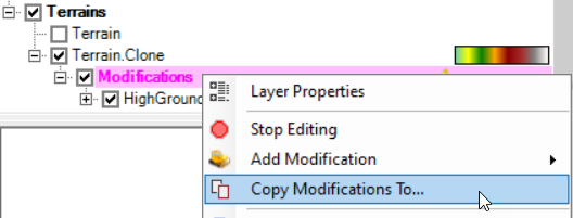
The user will then be prompted to select the RAS Terrain layer to copy the modification into.

Add New Modification Layer
The modifications have been organized into modification types based on function: simple Shapes, complex Lines, and complex Polygons. Simple Shapes allow the user to specify a single elevation override, while the more complex Lines and Polygons options allow you to use multiple elevations to control the development of a modification based on interpolation.
To add a modification layer to the Terrain, right-click on the Terrain layer and select the  Add New Modification Layer menu option to access the specific modification type of interest. Once a modification type has been selected, you will be prompted to provide a Name for the modifications layer. The new modification layer will be added to the Modifications group under the Terrain layer. Proceed by selecting the layer and create the individual modification features.

Once a modification layer is created, select the layer to create individual modifications (shape, line, polygon). When a modification is created you will be prompted to provide a Name, enter dimensions, and choose the Modification Method. An example dialog is shown below for the simple Triangle modification.

The Modification Method refers to how you want to apply the modification to the Terrain - "Replace Terrain Value" is the default method for most of the modifications. The modification method are listed below.
- Replace Terrain Value is used to override the Terrain elevation values.
- Higher (Terrain/User) Value evaluates the modification and the terrain and uses the higher of the values ("high ground option").
- Lower (Terrain/User) Value evaluates the modification and the terrain and uses the lower of the values ("channel option").
- Add Value to Terrain adds the modification value to the terrain ("builds a fence").
Simple Shape Modification
The Shapes group type is intended to be used for "simple" shapes that block out area using single elevation, like a pier that terminates into a bridge deck. There are four shape choices: Circle/Ellipse, Rectangle, Triangle, and Elongated Pier. To add a simple shape, select the  Add New Feature tool on the Edit Toolbar. A "preview" shape based on the default dimensions or previously added modification will appear to show the user what the modification will look like. A single click creates the shape in the modification group and an editor will be enabled to allow you to specify a Name, Modification Method, Elevation, shape dimensions, and Rotation Angle. Click OK to save the edits. At this point the shape can be moved and graphically modified (and rotated) using the
  Edit Features tool. To edit the modification parameters, right-click on the feature and choose Edit Modification. The editors for each modification type are shown below.
Circle/Ellipse Editor

Rectangle Editor

Triangle Editor

Elongated Pier Editor
The Elongated Pier Editor allows the user to specify a complex shape by specify the Length of the pier and the pier nose shape. Rounded and triangular options are available for the nose. The ability to rotate the pier, to align it with the direction of flow or to meet as-built specifications, provides additional flexibility the pier editor

Line Modifications
The Lines group type is intended to be used for complex elevation modifications for either High Ground or Channel bathymetric modification. The line is used to identify the alignment property, (e.g. the center of an elevated road or invert of a channel) while elevation data can be specified in multiple ways. Elevation data can then be applied to the line using a station-elevation approach (where the zero station is the start of the line) or using Elevation Control Points to set elevations along the line. A simple trapezoidal template for the cross section can then be applied along the line. A 3D centerline can also be imported from a shapefile.
To add a simple shape, use the Add New Feature to create a centerline for the modification. The centerline is completed by double-clicking to finish the line. To make modifications to the line at a later time, use the Edit Feature tool.

Once the line is completed, the Ground Line Editor (shown below) will be invoked to allow the user to define the elevation data and the cross section information. By default, elevation data will be "extracted" at the first and last point of the polyline to help assist tying in the modification to the existing ground surface elevations. If the line type is High Ground the modification method will default to use the Higher Value, while if the line type is Channel, the method will default to use the Lower Value.
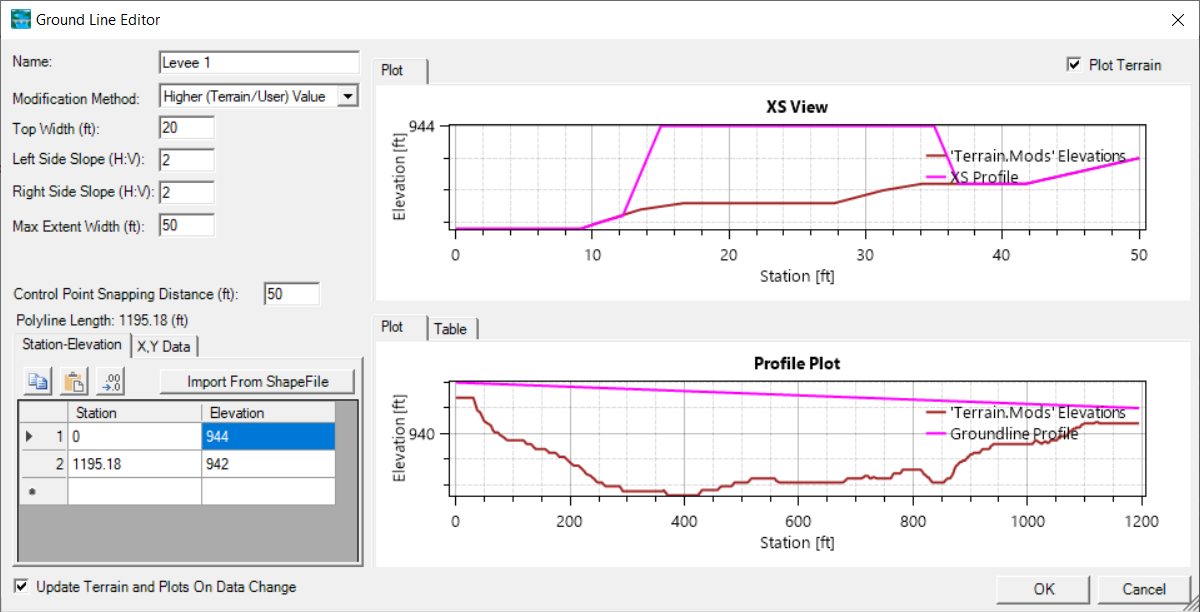
The upper portion of the editor allow you to control the cross section template to apply along the line. Top Width, Left Side Slope, Right Side Slope, and Max Extent Width describe the trapezoidal shape and area to influence around the line. The Station-Elevation data controls the interpolated elevation profile. As data is entered the cross section and profile plots will update to provide feedback on how the terrain will be modified.
If you possess a polyline shapefile (with or without elevations), you can import the features. The shapefile import is available by right-click on a line modification layer and selecting Import Features from Shapefile or using the Import from Shapefile button on the Ground Line Editor. If you are importing into/over an existing modification line, RAS Mapper will warn you that you will be replacing the XY data (and later, if Z-values are detected, you will warned that the Station-Elevation data will be replaced). The shapefile importer dialog will be invoked, allowing you to pick the shapefile to import and the feature(s) to import. Multiple features cannot be import through the Ground Line Editor. The Shapefile Importer will help the user visualize what data is available for import by previewing the data with a mini view of RAS Mapper, allowing you to choose the Terrain background.

Once the line and modification information are provided, RAS Mapper will automatically recompute the Terrain layer using the modifications.

For each "complex" modification type in RAS Mapper, a sub-layer is added to allow you to add Elevation Control Points. Elevation Control points allow you to set the elevation of the line based using point locations. While editing the Control Points layer, click on a location to assign and elevation. When attempting to create a point, if it is close enough to the line based on the Control Point Snapping Distance a cross will appear - if the cross does not appear, the point will not be used by the line. After each point is created, a dialog will appearing requesting an elevation override (with the current Terrain elevation already provided). Enter an elevation for the control point and click OK. The elevations from the control points will be used to interpolate values along the line modification.

System Name
A System Name field exists for utilizing National Levee Database data. RAS Mapper will automatically attempt to compute connectivity(Computed System Name attribute) from one high ground line to another. If line segments start/end close to each other (and have the same System Name) then the line segments be treated as a continuous feature and elevations will be interpolated together.
Interpolation Procedure
The High Ground interpolation procedure will create offset lines for each levee feature. There will be the centerline feature as defined in the feature table, a line on either defining the top width, and a line on either side defining the max extent. Those 5 lines are then used in a ribbon triangulation to interpolate along the length of the feature. An example for offset lines for multiple features (four levee features) is shown below. For the example below, the Transition Fraction property is not being used (value was set to 0).
Triangulation then occurs for each X,Y point along the offset lines, as shown in the example below.
Polygon Modification
The Polygons group type is intended to be used for complex elevation modifications for an area using multiple elevations to control the terrain surface. There are two options: Rectangle and Multipoint. The Rectangle option works like the simple shape version, but allows for Elevation Control Points to be added. The Multipoint option is more robust in that it allows you to draw a polygon to define the area to override terrain elevations and provides the option to use the elevations from the Terrain at the boundary of the polygon. By default the Use Elevations at Boundary from Terrain is checked, which will allow you to blend the polygon elevations with the base terrain elevations. Using the terrain elevations option will use the polygon to cut a profile from the terrain. The profile elevation points will then be triangulated. The resulting surface may not provide the desired outcome, at which point you can add Elevation Control Points to improve the triangulation.
After creating the polygon, an editor will allow for providing a name for the polygon modification, select the elevation method, and enter the tolerance for snapping Elevation Control Points. When using control points, any point placed inside the polygon will be used in triangulating the interior surface while points placed exterior to the boundary (within the snap tolerance) will be used to control the boundary elevation.

There are multiple elevation methods for the Perimeter Profile Mode.
- Terrain Elevations or Override with Control Points. This will allow you to match the perimeter to the existing terrain and then modify the interior interior elevations by specifying control points at specific locations. The control points are then triangulated to create a surface. This is the default method.
- Use Imported Z values. This method requires you to import a PolygonZ shapefile.
- Use Constant Elevation. This allows you to replace all data with the specified data.
National Levee Database (NLD) Data
The National Levee Database (NLD) is provided by the USACE and shares information for some 7,000 levee systems in the United States. The database contains information to facilitate and link activities, such as flood risk communication, levee system evaluation for the National Flood Insurance Program (NFIP), levee system inspections, flood plain management, and risk assessments. The NLD continues to be a dynamic database with ongoing efforts to add levee data from federal agencies, states, and tribes. NLD data can be accessed at https://levees.sec.usace.army.mil/#/.
HEC-RAS has incorporated the ability directly download and utilize NLD data within a RAS Terrain as a Terrain Modification. The NLD organizes data by Levee System and individual levee Segments. The Levee System is a continuous alignment line with elevations, while the levee Segment provided other information about the sections of the levee. Each levee Segment is comprised by a particular feature type (Centerlines, Floodwalls, and Closure Structures). There are additional features in the NLD; however, the information along the Levee System are the pieces of information (levee alignment and elevations) HEC-RAS will use for the Terrain Modification. A full description of the features available from the NLD area listed here: https://levees.sec.usace.army.mil/developer/#/features.
NLD Data Download
NLD data is can be retrieved using HEC-RAS using a web feature service request from the NLD.
To utilize the download tool, you must first define a Projection and zoom to the area of interest.
To access the NLD download tools in RAS Mapper, select the Project | Download Data | National Levee Database Features (NLD). Select the Extent Source (Current View is the default extent) and press the Query Products button. As shown below, a progress dialog will be invoked providing a status message.

Once the NLD has been queried, you will have the option of selecting levee information based on the the Levee System. The NLD organizes data by Levee System and HEC-RAS will allow you to identify download by Levee System.

By default, all of the available Levee Systems in the extent will be ready for download. Press the Download button to begin the download process. The NLD data are stored in multiple pieces of information. The Levee System line is a continuous line of elevation data along the levee. Individual feature segments hold attribute information such as top width and side slope. By default the data download process will apply the Elevation information from the Levee System line to the individual features ("Ensure Levee features have elevation data (from System Layer)") and will attempt to orient all of the levee Segments together in a consistent direction ("Ensure Levee features area oriented with System Layer"). (It is recommended you use the 'Ensure" options to bring in the elevations and orient the line segments. Not using these options will result in no elevations for the levee lines and they may not be connected appropriately as data gaps are created where data is missing or backwards.)
Downloaded data will be stored in the \Downloads\NLD folder by default. GeoJSON files for the NLD data will be stored for each set of features for data downloaded from the NLD. HEC-RAS will also create a shapefile for information specific to making high ground Terrain Modifications - named RASMergedAlignments.shp. Once the data are downloaded, press the Close button.
A new group layer name NLD will be added to the Map Layers in RAS Mapper with the complete NLD information. Features such as Leveed Area, Pump Stations, and Gravity Drains will be available to inform the HEC-RAS modeler. The NLD group will contain the RASMergedAlignments and all of the individual feature layers. The Merged layer is comprised of Levees, Floodwalls, Closure Structures, Roads, Railroads, High Ground, and Data Gaps (alignments with no features) according the NLD data. As shown in the figure below, the many features available from the NLD are listed as separate layers in RAS Mapper.

The attributes needed to created a terrain modification (Top Width, Left Side Slope, Right Side Slope) are added to the RASMergedAlignments layer. An example of the data table is shown below.

Using NLD for Terrain Modification
Once NLD data has been downloaded, the RASMergedAlignments shapefile can be used to create a Terrain Modification. The High Ground Terrain Modification line type is used to implement a levee alignment. As shown in the table above, the NLD data may not be "complete". Therefore, HEC-RAS will make some assumptions when creating the RASMergedAlignments layer. For the Terrain Modification routines to work, each line must have a Top Width and Side Slopes. Therefore, the "last known value" will be used for levee information by looking upstream (first) and then looking downstream. If information is missing for Floodwalls and Closure Structures a default width of 2.0ft and side slopes of 0.1).
Use a Clone of the Terrain prior to making a Terrain Modification.
To create Terrain Modifications using the NLD data perform the procedure listed below.
- Using a cloned Terrain, Add a Terrain Modification by right-clicking on the RAS Terrain layer and choosing Add New Modification Layer | Lines | High Ground.

- Provide a name (Levees, for example) for the modification layer. The modification will be in Edit mode.
- Right-click on the Levees modification and choose the Import Features menu item.
- Select the RASMergedAlignments shapefile (the shapes are PolylineZ) and Import the Levee Systems.
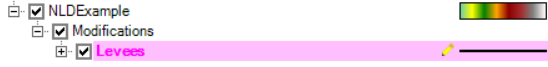
The High Ground (Levee) layer will be created from features imported from the merged layer. The levees are represented by the features from the NLD using the System Name for grouping the features. The Name attribute is used to identify the "type" of feature (Levee, Floodwall, Closure, ...). The attributes also indicate the way the feature will be used ("Take Higher") and the parameters for describing each line (Top Width, Left Side Slope, Right Side Slope, and Max Extent). While the top width and side slopes are taken from the NLD, the max extent default (area influenced by the levee modification) is computed using a multiple (4) of the top width. An example table is shown below.

The Computed System Name is internally computed by RAS Mapper to provide line connectivity. Lines that are considered to be part of the same system will be interpolated together as a continuous feature. This means that if a parameter is missing for a feature, it will use the value from the previous line segment. Further, the Transition Fraction attribute indicates how the interpolation will occur from one segment to another (as a multiplier of the width value). Blank or 0 value means there will be an abrupt transition. A value of 1.0 will use 100% of the width to transition to the next segment.
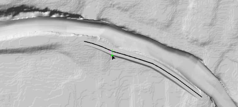
Elevations are stored as part of the individual features and used with the other attributes to create the vector terrain modification. An example of the modification is shown below.
Each individual levee alignment can be edited separately using the generalized editing tools and properties can be modified using the Ground Line Editor (shown below).
