Download PDF
Download page Workshop 1 – Watershed Setup & Network Development.
Workshop 1 – Watershed Setup & Network Development
Last Modified: 2023-02-07 06:48:22.762
Software Version
HEC-ResSim pre-release Version 3.5 will be used during the 2023 PROSPECT #098 course. Download here: https://drive.hecdev.net/share/YETr0az6
Workshop Instructions (PDF): Workshop 1 - WatershedSetupConfigurationsNetworks.pdf
Download Zipped Workshop Datafiles: Workshop 1 - Maps.7z & CrazyMountainData.xlsx
Introduction
This workshop will demonstrate watershed model setup capabilities and the integration of project elements and data in HEC-ResSim. Familiarity with creating stream alignments, configurations, and networks will be gained by constructing a project schematic for the fictitious Ventura River Basin. All physical elements, including Crazy Mountain reservoir, routing reaches, and junctions will be edited to incorporate required physical data.
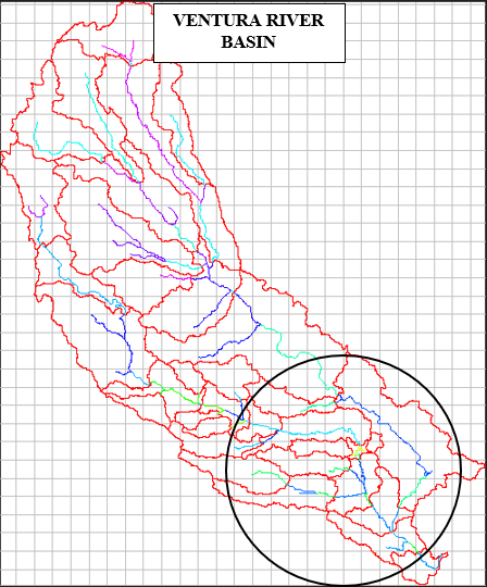
Figure 1.1 Workshop Project Area
Problem Description
The workshop goals are to:
- create a watershed configuration for an existing project
- create a new Network
- edit the properties of each physical element
- enter the respective hydraulic data provided in the CrazyMountainData spreadsheet
Stream and watershed background maps for the Ventura River Basin have been loaded on your workshop computers under C:\class\Workshop 1–Maps.
The watershed configuration consists of a single upstream reservoir, Crazy Mountain Lake, a main stem river, Ventura River, two tributaries, the Italian River and Oak River, and a few computation points along the rivers.
References:
CrazyMountainData.xlsx –
To simplify the data entry aspects of the exercise, the spreadsheet C:\class\CrazyMountainData.xlsx contains the values for the elevation-storage relationship and operating zone designations for Crazy Mountain Lake Reservoir, elevation-flow relationships for the penstock and emergency spillway, and Muskingum routing method parameters for specific reaches in the Ventura River Basin.
Crazy Mountain Reservoir Regulation Manual –
This document, CrazyMountainRegManual.pdf, describes the physical and operational characteristics of the Crazy Mountain reservoir. It is included in your course manual and can be found in PDF form in the C:\class folder on your workshop computer. You will need this document for this workshop.
Tasks
1. Launch HEC-ResSim.
2. Create a new watershed:
- Select New Watershed from the File Menu
- Make sure you are in Watershed Setup Module
- Name the watershed as Ventura
- For the location of the watershed data, use the drop down menu to select C:\class\My Watersheds.
- Select English Units.
- Click the Time Zones… button and select (GMT-08:00) Pacific Time for the Time Zone, press OK.
- Verify the Units System and Time Zone in the Watershed Summary window. If the information is incorrect, press the Back button and make the appropriate changes. Press OK when finished.
3. Open Windows Explorer and go to C:\class\My Watersheds\. (Notice that a subdirectory, Ventura, has been created.)
4. Add background map(s): shp and watershed.shp
- Using Windows Explorer, copy all the Map files provided in C:\class\Workshop 1–Maps to C:\class\My Watersheds\Ventura\maps
- In the Watershed Setup Module, select Layers… from the View menu. (This window can remain open for as long as you want to manipulate the view in the map window.)
Select Add Map Layer… from the Maps menu and a file browser window will display.

Tip
By resetting the Files of Type pull down menu at the bottom of the browser, you can simplify your selection list for the map layer you want to add.
Select river.shp and press OK.
- Repeat above to add watershed.shp
- The layers named river.shp and watershed.shp will appear in the Layer Selector window and in the background within the Watershed Setup Module. (Notice that the basin sub-watershed areas are filled with dark colors.)
- To remove the fill from each of the subbasin polygons, in the Layer Selector window, right-click on the watershed.shp layer and select Properties. In the Properties window, uncheck Display Fill. Press OK, then press Apply in the Layer Selector window.
- To make all segments of the rivers one color, right-click on the river.shp layer and select Properties. In the Properties window, make sure One Style is selected from the drop-down menu under Draw Features. Change the color to blue and press OK.
Press OK in the Layer Selector window to apply changes and close. The fill colors for the sub-watershed areas will be removed and the rivers will all be blue.

Note
Supported types of map files in HEC-ResSim include: USGS Digital Elevation Graphs (DLG), ArcView shapefiles (SHP), AutoCAD Digital Exchange Format (DXF), USGS Digital Elevation Models (DEM), Raster Image (IMG), ArcInfo ASCII grid (ASC), and ASCII NetTIN (NET).
Note
It is not necessary to display a map in the background. However, it is convenient to have a background map as a guide when creating stream alignments.
5. Draw the Stream Alignments
- Refer to Figures 1.1 (above) and 1.2 (below) for project area location, desired stream alignments and corresponding names.

Figure 1.2 Existing Project Configuration
Note
To move on to the next set of tasks and progress within the allotted time for this workshop, accuracy is not required in replicating the stream alignment shown in Figure 1.2 (below). Concentrate on following the general course of each stream element without worrying about having the stream alignment overlay the exact curves of the background stream layer.
- Using the Zoom tool
 , zoom into the general area shown in Figure 1.2.
 - Select the Stream Alignment tool
 from the left-hand toolbar. (The Stream Alignment Tool button will appear depressed).
 - Your first point will be the upstream end of the Crazy Mountain Lake (on the main stem Ventura river and upstream from Crazy Mt. Inflow JCT)
- Press and hold the CTRL key while you place the cursor above the first point, click the left mouse button, and continue to hold the CTRL key as you progress from upstream to downstream, clicking at each succeeding point of inflection to draw the alignment.
- To drop the last, downstream-most point of the stream alignment (downstream of River Pointe), release the CTRL key before positioning the cursor and clicking the mouse. A window will appear asking for you to name the stream you just drew. Type Ventura River in the name field and press OK.
Repeat the above steps for each of the two primary tributaries and name them appropriately. (Italian River and Oak River. See Figure 1.2) At the end point of the tributaries, ResSim will prompt you to join the tributary with the existing main branch. This will provide connectivity between the rivers.
Tip
You can insert additional vertices to the alignment by double-clicking on an existing stream (the stream line will turn red and the vertices will appear blue). Then hold down the CTRL key and click at each location you want to place a new vertex. Now each blue point can be dragged and moved to better shape the line.
- To save the alignment, select Save Watershed from the File menu.
6. Create a Configuration
- From the Watershed menu, select Configuration Editor.
- From the Configuration menu in the Configuration Editor, select New to bring up the new configuration window.
- Enter the name of the configuration as Existing, select 1hour for the time step, and press OK to exit the New Configuration window.
- Press OK to exit the Configuration Editor.
- From the Configuration dropdown on the tool bar below the main menu bar select your new configuration (Existing).
7. Add elements to your configuration.
- Refer to Figure 1.2 for the desired location of the reservoir.
- Select the Reservoir tool
 (the Reservoir tool will appear depressed).
 - While holding down the CTRL key, place the cursor at the desired upstream extent of the reservoir pool and click on the left mouse button.
- Release the CTRL key, move the cursor to the location of the dam, and click the left mouse button again.
- A window will appear asking you to name the reservoir. Name the new reservoir Crazy Mountain and press OK.
These steps will cause a wide cyan-colored line, a transparent cyan-colored triangle, a grey rectangle, and two black computation points to be drawn between the two points you selected on the stream alignment. The wide cyan line represents the reservoir pool, the grey box represents the dam, and the black computation points represent the inflow point to the pool and the tailwater of the dam. The transparent triangle is a re-shapeable polygon that you can use to outline the reservoir pool in the map region.
- Verify that editing is allowed within the Watershed Setup Module by hovering the cursor over the yellow lock on the tool bar menu.
Tip
To alter the stream alignment without impacting the location of the reservoir, the reservoir can be anchored by adding two straddling Stream Nodes (one on the upstream side of the Reservoir and the other on the downstream side). To add a stream node just upstream or just downstream of the reservoir, first click on the Stream Node tool. Then, depress the CTRL key and move the cursor to the desired location and drop the stream node by clicking on the left mouse button.
- Save the configuration by selecting Save Configuration from the Watershed menu.
8. Add the necessary computation points to the configuration
- Select the Computation Point tool.
 (The Computation Point tool will appear depressed.)
 - Rename the upstream and downstream computation points as Crazy Mt. Inflow JCT and Crazy Mt. Outflow JCT, respectively, by right-clicking on each computation point and selecting Rename Computation Point… from the popup menu.
- Refer to Figure 1.2 for locations of the rest of the desired computation points (represented by black dots) and their corresponding names
- While holding down the CTRL key, place the cursor at the desired location and drop a computation point by clicking on the left mouse button.
- Release the CTRL key and name the computation point.
- For the computation points at the confluences of the Ventura/Oak and Italian Rivers, select a placement of “At the Stream Junction” from the drop-down menu before closing the dialogue.
Tip
When adding a computation point at or near a confluence, there is the option to choose where the computation point will be placed. Typically, the appropriate choice is “At the Stream Junction”.
- Repeat these steps for the rest of the computation points illustrated in Figure 1.2.
Tip
Renaming computation points can be done by right-clicking on the computation point and selecting the rename option from the popup menu.
- Save the Configuration (from the Watershed menu) and Save the Watershed from the File menu.
9. Create a new Network:
- Select Reservoir Network from the Module drop down menu
- Select Network_New from the menu bar, and a Create New Reservoir Network window will open
- Name the new network as 01 Standard, and add a description. Select the configuration called Existing, and press New. Notice that the computation points (black dots) from the configuration are imported to the network as junctions (red dots).
10. Complete Network Connectivity:
- Using the reach tool
 , press the CTRL key and click on an upstream junction. Release the CTRL key and click on the downstream junction. (The new reach element will be drawn on top of the stream alignment with a heavy blue line.)
 - A box should appear showing a suggested name for the reach. Edit the default reach name to match what is suggested in the "reach name" column in Table A.1 of the Regulation Manual. Or, you may prefer pasting the names from version of the information found under the "WS#1 Reach Properties" tab of the CrazyMountainData.xls spreadsheet.
- If for some reason the reach ends up with the wrong name, right-click on it and select Rename from the popup menu to rename the reach.
- Repeat these steps to connect the remaining Junctions in the Network with reaches.
11. Enter Reach properties:
- Using the reach tool
 or pointer tool
  , right-click on each reach and select Edit Reach Properties. In the Reach Editor, select the routing method (Muskingum) using the drop down arrow next to Method and fill in the necessary parameters with the value from the "Muskingum Routing Parameters" column under the "Reach Properties" tab of the CrazyMountainData spreadsheet. The drop-down menu beside Reach Name in the Reach Editor can also be used to select the different reaches.
12. Edit properties for Junctions that will receive local inflows:
- Using the junction tool
 or pointer tool
  , right-click on a junction, and select Edit Junction Properties. The Junction Editor should appear.
 - Select one of the junctions listed in Table A.2 of the Regulation Manual that has local inflow. Note that Table A.2 shows two junctions that receive no inflow. Drainage above these points is lumped in with local inflow at the next downstream junction. For example, the local inflow assigned to junction "Greenfield" includes Italian River drainage below "Villanova", and Ventura River drainage below "Rockville".
- Right click the junction and select Edit Junction Properties.
Select the Local Flow tab and input a name and factor, for the external flow entering the junction, as shown in Table A.2. Choose the names with care, because they are used as "location identifiers" that link to a DSS time series path. Also note that each junction may reference several "location identifiers," which are summed to determine the local inflow at the junction.
Tip
Local Inflow must be supplied at all headwater junctions, but it is optional at all other junctions.
- Input names and factors for the rest of the junctions that are assigned local inflow. Make sure to select the appropriate Junction from the drop-down menu at the top of the Junction Editor before entering the local flow name and factor. Press OK when finished.
Tip
The factor value entered in the Junction Editor can be used to adjust the magnitude of flows for a specified time series in order to spread that flow to multiple inflow locations. For example, a review of the subbasin map shows that the subbasin inflow representing the local at Greenfield could be shared at Ventura+Italian. Using basin area weighting, factors of approximately 0.2 and 0.8 could be used to apportion the total subbasin flow between the two junctions, "Greenfield" and "Ventura + Italian. Another use of the factor might be to estimate local inflow to an ungaged catchment by scaling up or down the inflow used at a nearby gaged catchment.
13. Enter the Physical Reservoir Data:
- Using the reservoir tool
 or pointer tool
  , right-click on Crazy Mountain Reservoir and select Edit Reservoir Properties and the Reservoir Editor will appear.
 - Select the Physical tab, and in the Crazy Mountain Reservoir Tree, right-click on “Dam at Ventura River” and rename it to just “Dam”. Press OK.
Add Pool Data
- From the Reservoir Tree in the Physical tab, click on Pool, and fill in the Elevation-Storage-Area table in the editor panel with the data provided in Table A.3 of the Regulation Manual (also available under the "WS#1 Reservoir & sub-elements" tab of the spreadsheet).
- Press Apply to approve changes and keep the Reservoir Editor open.
Add Dam Data
- In the Reservoir Tree, left-click on Dam and enter the elevation and length at top of dam, 743 feet and 1,400 feet, respectively.
- Add a controlled outlet by right-clicking on Dam and selecting the Add Controlled Outlet A controlled outlet will be added to the Reservoir Tree under Dam. Click on the Controlled Outlet and fill in the Elevation-Flow table with the data provided in Table A.4 of the Regulation Manual (also available under the "WS#1 Reservoir & sub-elements" tab of the spreadsheet).
- Add an uncontrolled spillway by right-clicking on Dam and selecting the Add Uncontrolled Outlet An uncontrolled outlet will be added to the Reservoir Tree under Dam.
- Click on the Uncontrolled Outlet, choose the Elevation vs. Outflow option, and fill in the Elevation-Outflow table with the data provided in Table A.5 of the Regulation Manual (also available under the "WS#1 Reservoir & sub-elements" tab of the spreadsheet).
- Press Apply to approve your changes
- Save the Network and the Watershed by selecting Network ->Save and then File ->Save Watershed from the menu bar.