Download PDF
Download page Moments.
Moments
Background
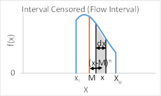
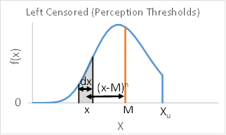
The general equation for expected moments is provided below. The concept is illustrated in Figure 1 and Figure 2 for a flow interval and a perception threshold, respectively. The equation is basically a weighted average calculation expressed using integrals because the frequency curve f(x) is a continuous function.
$E\left[(X-M)^{n}\right]=\frac{\int_{X_{l}}^{X_{u}}(x-M)^{n} f(x) d x}{\int_{X_{l}}^{X_{u}} f(x) d x}$


Moments are calculated with respect to a fixed reference point. The reference point used for expected moments is the mean (μ) of the frequency curve. This is called a central moment. In engineering mechanics, this is equivalent to calculating moments using the centroid of the object as the fixed reference point. In probability, the object is the frequency curve defined by the probability density function f(x) and the mean is located at the centroid of f(x).
https://en.wikipedia.org/wiki/Moment_(mathematics)
https://en.wikipedia.org/wiki/Moment_(physics)
https://en.wikipedia.org/wiki/Central_moment
The zero moment (n=0) is a probability and is equivalent to the mass of an object in engineering mechanics. This is the reason f(x) is called a probability density function. The mass of an object is equal to the integral of its density. This probability can also be thought of as the area under the probability density function where the integral ∫ f(x) dx is the area under the f(x) curve. The first moment (n=1) is the mean of the frequency curve and is analogous to the centroid of an object in engineering mechanics. The second moment (n=2) is the standard deviation of the frequency curve and is analogous to a moment of inertia in engineering mechanics. The third moment (n=3) is the skew of the frequency curve.
Exercise
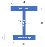
The centroid (first moment) for the beam shown in Figure 3 has been calculated relative to the reference point y=0. For each of the beam segments, the distance (D) is equal to the vertical distance between the centroid of the segment and the reference point. Since the reference point is at y=0, this distance is simply the y-coordinate.

Table 1. Total Beam Centroid
Segment | Height (H) | Width (W) | Area (H*W) | Distance1 (D1) | A*D1 |
|---|---|---|---|---|---|
Top Flange | 1 | 12 | 12 | 23.5 | 282 |
Web | 22 | 0.5 | 11 | 12 | 132 |
Bottom Flange | 1 | 10 | 10 | 0.5 | 5 |
∑A | 33 | ∑A*D1 | 419 | ||
yc = ∑A*D1 / ∑A | 12.7 |
Question 12. Calculate the first moment (centroid) for only the top flange and web segments of the beam using the centroid of the total beam (yc=12.7) as the reference point. For each beam segment, the distance (D) is now equal to the vertical distance between the centroid of the segment and the centroid of the total beam.
Table 2. First Moment of Top Flange and Web Segments About the Centroid of the Total Beam
Segment | Height (H) | Width (W) | Area (H*W) | Distance1 (D1) | A*D1 |
|---|---|---|---|---|---|
Top Flange | 1 | 12 | 12 | (23.5-12.7)1 | 129.6 |
Web | 22 | 0.5 | 11 | (12-12.7)1 | -7.7 |
∑A | 23 | ∑A*D1 | 121.9 | ||
X-M1 = ∑A*D1 / ∑A | 5.3 |
Question 13. Calculate the second moment (moment of inertia) for only the top flange and web segments of the beam using the centroid of the total beam (yc=12.7) as the reference point. The moment of inertia of a rectangle about the centroid of the rectangle is equal to wh3/12. The parallel axis theorem can be used to transfer the moment of inertia from on reference point to another. The equation is I = Ic + Ar2 where Ic is the moment of inertia about the centroid, A is the area, and r is the distance between the two reference points. In this example, r is the vertical distance between the centroid of the beam segment and the centroid of the total beam.
Table 3. Second Moment of Top Flange and Web Segments About the Centroid of the Total Beam
Segment | Height (H) | Width (W) | Area (H*W) | Ic = WH3/12 | r | I |
|---|---|---|---|---|---|---|
Top Flange | 1 | 12 | 12 | 1 | 10.8 | 1401 |
Web | 22 | 0.5 | 11 | 444 | -0.7 | 449 |
∑I | 1850 |
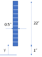
Question 14. Calculate the second moment (moment of inertia) for only the web segment of the beam using the centroid of the total beam (yc=12.7) as the reference point. Perform the calculation by dividing the web segment into 11 equal slices, as shown in Figure 2.

Table 3. Second Moment of Web Segment About the Centroid of the Total Beam
Slice | YMidpoint | Height (H) | Width (W) | Area (H*W) | Distance2 (D2) | A*D2 |
|---|---|---|---|---|---|---|
1 | 2 | 2 | 0.5 | 1 | 114.49 | 114.49 |
2 | 4 | 2 | 0.5 | 1 | 75.69 | 75.69 |
3 | 6 | 2 | 0.5 | 1 | 44.89 | 44.89 |
4 | 8 | 2 | 0.5 | 1 | 22.09 | 22.09 |
5 | 10 | 2 | 0.5 | 1 | 7.29 | 7.29 |
6 | 12 | 2 | 0.5 | 1 | 0.49 | 0.49 |
7 | 14 | 2 | 0.5 | 1 | 1.69 | 1.69 |
8 | 16 | 2 | 0.5 | 1 | 10.89 | 10.89 |
9 | 18 | 2 | 0.5 | 1 | 28.09 | 28.09 |
10 | 20 | 2 | 0.5 | 1 | 53.29 | 53.29 |
11 | 22 | 2 | 0.5 | 1 | 86.49 | 86.49 |
∑A | 11 | ∑A*D2 | 445 |
Question 15. Compare the two estimates of the second moment for the web segment.
They aren't exactly the same, but they are similar.