Download PDF
Download page The Reservoir Network Reports.
The Reservoir Network Reports
In the Reservoir Network module, the Reports menu provides access to summary reports pertinent to the elements in your active network. Each report includes a table containing the list of information pertinent to that report. In addition, Advanced reports describing your network connectivity are also available.
For information about printing and exporting options available from each report's Report menu, see "Printing and Exporting ResSim Data".
Sorting a Report Table:
In most reports, if you click on a column header of the table, the contents of the table will resort alpha-numerically based on the content of that column.
The Reservoir List
The Reservoir List ("Figure: Reservoir Network Reports - Reservoir List") displays the names, descriptions, and operations of all reservoirs in your network. Additionally, the number of reservoirs is listed in the bottom right corner. For information about printing and exporting options available from the report's Report menu, see "Printing and Exporting ResSim Data". The Edit menu provides access to the Reservoir Editor (after selecting a reservoir in the list and then selecting Edit from the Edit menu).

Figure: Reservoir Network Reports - Reservoir List
The Reach List
The Reach List ("Figure: Reservoir Network Reports - Reach List") displays the names, descriptions, routing method, and losses of all reaches in your network. For information about printing and exporting options available from the report's Report menu, see "Printing and Exporting ResSim Data". The Edit menu provides access to the Reach Editor (after selecting a reach in the list and selecting Edit from the Edit menu).
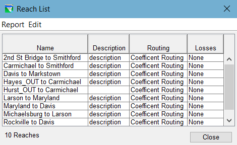
Figure: Reservoir Network Reports - Reach List
Finding Schematic Elements:
In large or unfamiliar models, it can be difficult to locate a specific model element. The network summary reports are a great tool for this. Find the element you are looking for in the report list and click on it to select it. When an element is selected in the report listing, that element is highlighted in the Map Display area.
The Junction List
The Junction List ("Figure: Reservoir Network Reports - Junction List") displays the names and descriptions of all junctions in your network. For information about printing and exporting options available from the report's Report menu, see "Printing and Exporting ResSim Data". The Edit menu provides access to the Junction Editor (after selecting a junction in the list and selecting Edit from the Edit menu).
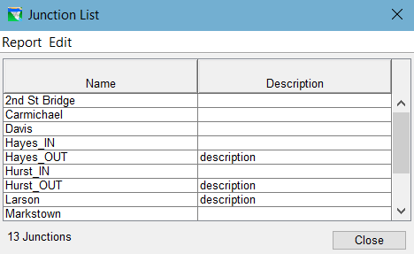
Figure: Reservoir Network Reports - Junction List
Deleting Schematic Elements:
If you encounter a circumstance in which you want to delete an element that you either cannot find or select in the Map Display area or you want to delete several element at once, the network summary reports can come in hand for this too. Select the element(s) you want delete in the table, then select Delete from the report's Edit menu.
The Diversion List
The Diversion List ("Figure: Reservoir Network Reports - Diversion List") displays the names, descriptions, and method of all diversions in your network. For information about printing and exporting options available from the report's Report menu, see "Printing and Exporting ResSim Data". The Edit menu provides access to the Diversion Editor (after selecting a diversion in the list and selecting Edit from the Edit menu).
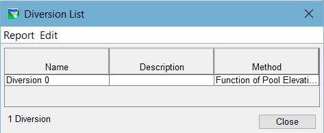
Figure: Reservoir Network Reports - Diversion List
The Advanced Reports
Two Advanced Reports are available from the Reports menu—Network Connectivity and Node List. These reports each describe how the model schematic is connected.
The Network Connectivity Report
The Network Connectivity report provides a detailed list of the elements (and sub-elements) that make up the model schematic of the active reservoir network. This report is complicated and requires that you understand 1) the concepts of elements, sub-elements, and the nodes that connect them and 2) how the report is arranged to identify the elements, their sub-elements, the connecting, and the connections.
This report uses row shading to indicate grouping of sub-elements within other elements. The rows identifying parent or primary schematic elements have a grey background. If a primary element contains sub-elements, those sub-elements will have a light grey background. The connection nodes of an element or sub-element have a white background and immediately follow the element or sub-element they pertain to.
The headers for each column identify their contents, however, some of the headers include two labels separated by a slash (/). The first label applies to the data in the grey or light grey rows (the elements and sub-elements). The second label applies to the data in the white rows (the nodes). The column headers include:
Element/Node—the element or node type. These include:
- JunctionElement—a Junction element; a primary schematic element. As far as the network connectivity is concerned, junctions do not have physical sub-elements. However, they do have virtual sub-elements—local inflows—which show up in the network connectivity report as inflow nodes at the junction.
- ReachElement—a Reach element; a primary schematic element. As far as the network connectivity is concerned, reaches do not have sub-elements and, when connected properly, they have only one inflow and one outflow node.
- DiversionElement—a diversion; a primary schematic element. Diversions are a bit more complex than junctions or reaches; they do contain sub-elements. Every diversion has one sub-element named Ctrl which identifies
- ReservoirElement—a reservoir; a complex element in the network that contains other sub-elements.
- If a sub-element of the reservoir is a complex element with sub-elements of its own, it may be one of the following:
- ReservoirDamElement—the dam. The dam contains at least two sub-elements by default—Tailwater and L&O.
- DivertedOutletElement—a diverted outlet that was added to the reservoir. Like the dam, it will have a "tailwater" sub-element and, if connected back into the network at its downstream end, it will also have a "reach" element.
- OutletGroupElement—an outlet group added to the dam, diverted outlet, or another outlet group.
- If a sub-element of the reservoir or of one of its complex sub-elements is a simple element with no sub-elements of its own, it will be labeled Element and may represent one of the following:
- The Pool—the storage element of the reservoir
- The Tailwater junction—the collector of the various release elements of the dam or diverted outlet
- The L&O—the default release element of the dam that represents Leakage (if specified) and Overflow.
- An Outlet—a release element added to the dam or to an outlet group
- If a sub-element of the reservoir is a complex element with sub-elements of its own, it may be one of the following:
- ID—the number of the element or node
- Name—the name of the element or node. Elements will show either the name you gave the element or the name ResSim assigned to it—like Pool for the reservoir pool element. Nodes that represent a local inflow at a junction will show the name you gave to the local inflow. All other nodes are assigned a name in the form ~Enn where nn usually relates to the element number of the parent element of the node.
- Function/Upstrm Elem—Elements will indicate the purpose of the element, e.g., the function of a controlled outlet is AdjustableFlow.
Nodes will identify the ID number of the element upstream of the node. - Parent/Dnstrm Elem —Sub-elements will indicate the name of the parent element to which the sub-element belongs. If blank, the element is a primary element.
Nodes will identify the ID number of the element that is downstream of the node.
Note: the purpose of the Network Connectivity Report is to show how all the network elements are connected through the inflow and outflow nodes listed with each element. But to fully understand the report you need to know a few things:
- Every element has an outflow node that "belongs" to that element; that node will always show the ID number of the element it belongs to (or one of that element's sub-elements) as the upstream element.
- Local inflows appear as inflow nodes at junctions; these nodes display blank for the upstream element.
- Inflow nodes almost always "belong" to an element other than the element in which they are listed as an inflow node. The exceptions to this are:
- Diversions are treated as negative inflows at junctions. Thus, Diversion elements place an inflow node at the junction from which they remove water and that node appears as an outflow node in the diversion element. That's bad enough but this oddity also shows up in the upstream and downstream element ids. The inflow node that represents the flow going to the diversion has the diversion element id as the upstream element; and that same node, listed as an outflow node at the diversion, has the ID number of the junction element it is taking water from as the downstream element.
- Reservoir sub-elements that represent a group of outlets (dam, outlet group, or diverted outlets) act like a passthrough element for the elements they contain; thus, the inflow nodes listed in the dam are also inflow nodes to the outlets they contain, even if those outlets are contained in an outlet group. In addition, each group-type element contains a junction sub-element that collects the outflow nodes of the outlets into a single outflow that then appears as the outflow node of the (internal) junction and of the group.
To generate a Network Connectivity report for all elements in the active network:
from the Reports menu, select Advanced → Network Connectivity → All Elements ("Figure: Reservoir Network Reports - Advanced - Network Connectivity - "All Elements"")
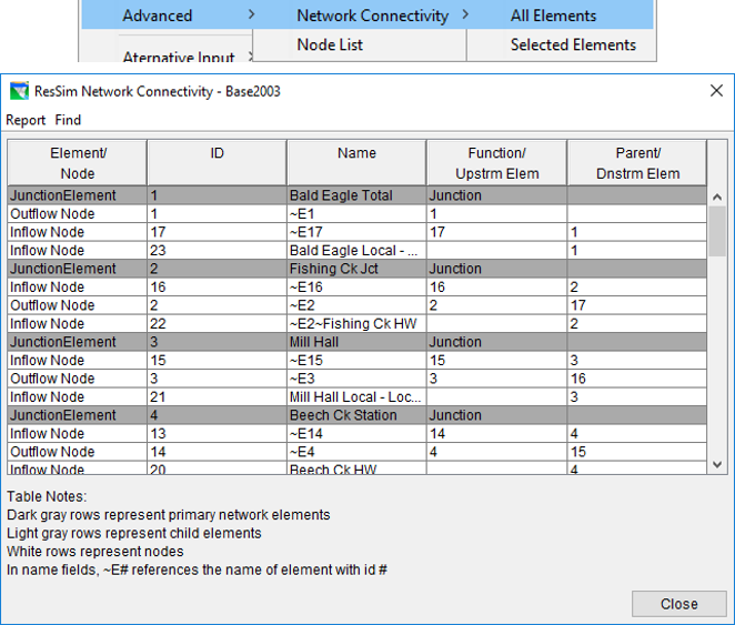
Figure: Reservoir Network Reports - Advanced - Network Connectivity - "All Elements"
To generate a Network Connectivity report for a set of selected elements:
First, select elements you want in the report by holding down the Shift key and clicking on the desired elements in the Map Display area (holding the Shift key allows you to select multiple schematic elements as indicated in the map shown in "Figure: Selection of Multiple Schematic Elements").
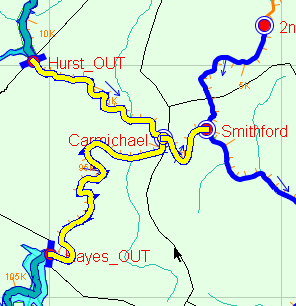
Figure: Selection of Multiple Schematic Elements
- Then, from the Reports menu, select: Advanced → Network Connectivity → Selected Elements. The report will look just like the one shown in "Figure: Reservoir Network Reports - Advanced - Network Connectivity - "All Elements"" but will only contain information for those elements you selected in the Map Display area.
The Find menu of the Network Connectivity report allows you to search for text strings within the report.
The Node List
The second advanced report is the Node List ("Figure: Reservoir Network Reports - Advanced - Node List"). This report provides a summary of all nodes in your reservoir network. Details include the Node ID, Name, Key String, Upstream Element, Downstream Element, Stream, Stream Station, and Stream Coordinate (i.e., a normalized position on the stream).

Figure: Reservoir Network Reports - Advanced - Node List
To generate a Node List report:
from the Reports menu, select Advanced → Node List
The Edit menu provides two options: Clean Network and Delete Node. These options can potentially damage a working network and should only be used when recommended by a ResSim technical expert.