Download PDF
Download page Configuring the OSI (and Your Alternative) to Compute Local Inflows.
Configuring the OSI (and Your Alternative) to Compute Local Inflows
To compute incremental local inflows from total flows requires that your network and alternative, as well as the OSI, be configured carefully. The basic steps you need to perform are described below.
NOTE—If your objective is to compute local inflows from observed data for use in a complex study model, see Preparing Your Study Model for Computing Local Inflows for additional considerations and instructions for configuring your network and alternative.
Prepare the Alternative and Its Network
The equation used by ResSim to compute incremental local flow is:
Local Flow = Total Flow – Routed Flow
Where:
- Local Flow is the incremental local flow at the junction.
- Total Flow is the total flow leaving the junction; more specifically, it is the Observed flow at the junction.
- Routed Flow is the flow routed to the junction from upstream; more specifically, the upstream Observed flow routed to the junction.
In order to provide the correct information to the junction to compute the local flow, some changes may be necessary in both the reservoir network and the alternative.
The configuration requirements include:
- Local Flow cannot be computed at headwater junctions since ResSim cannot route flow to these junctions. However, if an Observed flow is provided at a headwater junction, it will be used instead of the total inflow for the computation of local flow downstream.
- Only one incremental local flow can be computed per junction element. Each junction should have no more than one entry on the Local Flow tab of the Junction Editor.
- An Observed flow must be associated with each junction where local flow will be computed.
- An Observed flow (representing the reservoir release) must be associated with the outflow junction of each reservoir upstream of a junction where local inflow will be computed.
To accomplish these requirements:
Review the local inflow tab of each junction in your network. For any with more than one inflow defined, replace the set with a single composite inflow—e.g., use a flow-local output from an HMS junction rather than multiple subbasin flows. If a composite external time series option is not available, consider modifying the network to add additional junctions to receive the various locals—e.g., if one of the local inflows is a reach flow coming from a tributary in HMS that is not currently represented in ResSim, add the tributary and a junction at its mouth (to receive the reach flow) to the ResSim network.
At each junction where you want ResSim to compute an incremental local and at each outflow junction of the reservoir above the junctions where you want incremental local flow computed, place a checkmark on the Observed tab of the junction editor to indicate that you have observed data for the total Flow from the junction ("Figure: Junction Editor—Activate Observed Data for Total Flow").
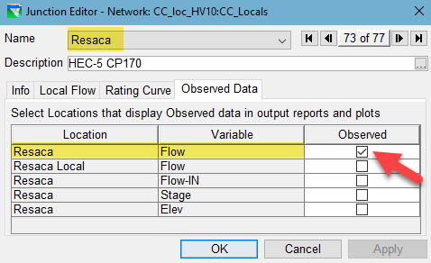
Figure: Junction Editor—Activate Observed Data for Total Flow
- Save the network.
- Open the Alternative Editor. Select the alternative to be used for computing local flows. This should be the same as or a copy of the real-time or study alternative that will be using the local flows.
On the Observed Data tab, identify an observed total flow time series for each junction's total flow variable in the list. Unless needed for other purposes, leave all other listed entries blank.
Figure: Junction Editor—Activate Observed Data for Total Flow
On the Time Series tab, identify an input time series for each inflow in your model. This may mean changing some entries that are already filled-in as well as filling-in the blank entries.

Caution
You may think that because ResSim is going to compute most of the inflows listed on the Time Series tab of the Alternative Editor, you can use a single dummy time-series record for each local inflow that will be computed. Unfortunately, you would be wrong!
Each inflow must have a uniquely named time series record associated with it in the Time Series tab of the Alternative Editor. This is because ResSim is going to write the locals that are computed by the OSI into that record in the simulation. If you do not have a unique time series for each location, create one and fill it with a constant value for the full time window over which you have observed data and for which you will be computing the locals.
OSI Configuration
ResSim and the OSI will only compute incremental local flow for those locations represented by an OSI Local Inflow variable.
The OSI can only be configured for a computed alternative in the Simulation module, so that where you must start:
- Open or create a simulation that spans the time window of the observed data. If the local inflow computation is for a real-time alternative, the time window should include the forecast period.
- Add your alternative to the simulation and compute it.
- Open the OSI and create a Local Flow tab. You may need more than one tab so consider creating a tab for the local flows within each major tributary of your watershed.
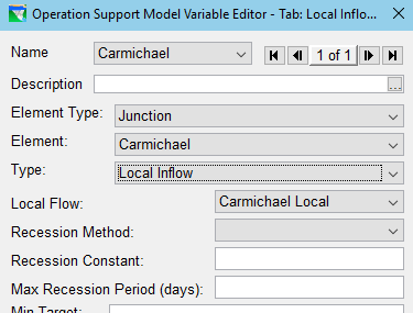
Figure: OSI Variable Editor—Defining a Local Inflow Variable
For each incremental local inflow you want to compute:
- Create an OSI variable.
- In the OSI Variable Editor…
- Set its Element Type to Junction.
- Select the particular junction Element.
- Set the variable Type to Local Inflow.
- The Local Flow field will fill with the first (and hopefully, only) local flow listed on the Local Flow tab for that junction in the Junction Editor.
- If you are computing locals from observed data for use in a study, you can leave the Recession Method and its parameters blank. However, if you are computing the locals for use in a real-time alternative, then select the Recession Method and specify the Recession Constant and the Max Recession Period in days.
- Click Apply in the OSI Variable Editor to save your settings, then set the data in the rest of the editor to configure the plot of the variable. Add one or more variables to be plot with the local flow so that you can see and analyze the validity of the computed local flow. Suggested variables to add to the plot include: total computed junction flow and observed junction flow.
- Click Ok when you are finished with the current local inflow variable and close the OSI Variable Editor.
- Repeat these steps until you have created an OSI Variable for each local inflow to be computed.
- Once you have created an OSI variable for each local flow to be computed, save the OSI configuration. You may also want to copy the alternative back to the network module so that your OSI configuration can be used in other simulations. To do so, close the OSI, then right-click on the alternative in the Control Panel and select Save to Base Directory… from the context menu.
- You should now be ready to compute the local flows. See "Computing Local Flows" for instructions.