ResSim has a two default layers, the Schematic layer, and the Stream Alignment Layer. These layers are described in the following sections.
The Time-Series layer was removed in ResSim 3.3.
Schematic Layer
The Schematic Layer has a different name, contains different component layers, and uses different display properties in each module of ResSim:
- In the Watershed Setup module, the schematic layer is called Study.
- In the Reservoir Network module, the schematic layer is called ResSim.
- In the Simulation module, the schematic layer is called Model Schematic.
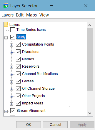
Study Layer
The Study layer is the schematic layer that is displayed in the Watershed Setup module of ResSim. The Study layer contains all of the schematic elements that you can define in your watershed configurations including the various project types, impact areas, and computation points. The elements displayed by the Study layer in the Map Display area are a function of the currently selected Configuration.
When you are in the Watershed Setup module, the Layer Selector includes Study as a primary layer in the Layers tree ("Figure: Study Layer").
When you click on the plus sign in front of the Study layer in the Layers tree, the layer expands to show the set of component layers contained in the Study layer, including:
- Computation Points
- Diversions
- Names (labels for the projects, computation points, and impact areas)
- Reservoirs
- Channel Modifications
- Levees
- Off Channel Storage
- Other Projects
Impact Areas
ResSim creates a sub-layer for each component types even before you have defined any projects, computation points, or impact areas. Each component layer can be turned on and off without impacting the display of the other components.
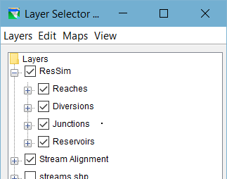
ResSim Layer
The ResSim layer ("Figure: ResSim Layer") is the schematic layer that is displayed in the Reservoir Network module of ResSim. The ResSim layer contains all of the schematic elements that you can define in your reservoir networks. However, the elements displayed in the Map Display area of the Reservoir Network module as represented by the ResSim layer are a function of the currently open reservoir network; if no network is open, only the stream alignment and map layers will be shown in the Map Display area and in the Layers tree of the Layer Selector.
When you are in the Reservoir Network module, the Layer Selector includes ResSim as a primary layer in the Layers Tree. When you click on the plus sign in front of the ResSim layer in the Layers Tree, the layer expands to show the set of component layers contained in the ResSim layer, including:
- Reservoirs
- Reaches
- Diversions (and Diverted Outlets)
- Junctions
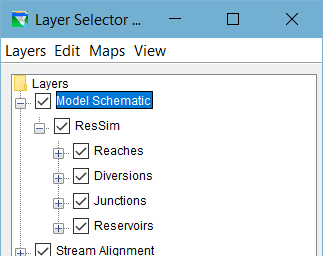
Model Schematic Layer
The Model Schematic layer ("Figure: Model Schematic Layer") represents the model schematic in the Simulation module. It contains the ResSim layer and its component layers as described above.
When you are in the Simulation module, the Layer Selector includes Model Schematic as a primary layer in the Layers tree.
The elements drawn in the Map Display area of the Simulation module as represented by the Model Schematic layer are a function of the currently active alternative. If no alternative is active, only the stream alignment and map layers will be shown.
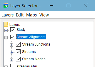
Stream Alignment Layer
The Stream Alignment layer contains the Stream Alignment which represents the river system in your watershed. The Stream Alignment layer includes three component sub-layers ("Figure: Stream Alignment Layer"):
- Streams
- Stream Nodes
- Stream Junctions
The Stream Alignment layer is available in the Layer Selector in all three ResSim Modules.