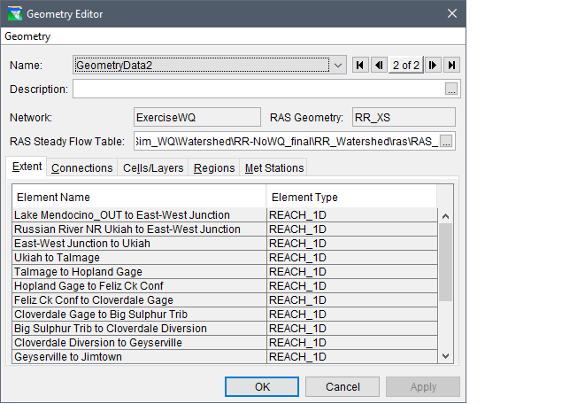
The first tab in the Geometry Editor (Figure 4.14) is the Extent tab (Figure 4.17). This tab displays a list of the elements in the geometry's geographic extent. The Element Name (Figure 4.17) column and associated Element Type (Figure 4.17) column contains the list of elements provided by the linked HEC-ResSim network (selected at the creation of the geometry dataset as described in Section 4.4). The Element Name column displays all the reaches and reservoir names in the extent. The Element Type column lists the type of element that is displayed in the row, either reach (REACH_1D) or reservoir (RESERVOIR_1DV).
By default, the elements are listed in hydrologic order (upstream to downstream), but the user can click the top of the columns to sort the table alphabetically by either column. The table cannot be modified from the Geometry Editor (Figure 4.14). However, the geometry's geographic extent can be reduced (by default, all of the elements in the entire HEC-ResSim network in included in the geometry) from the HEC-ResSim main window (Figure 4.1), from the map window schematic display area.
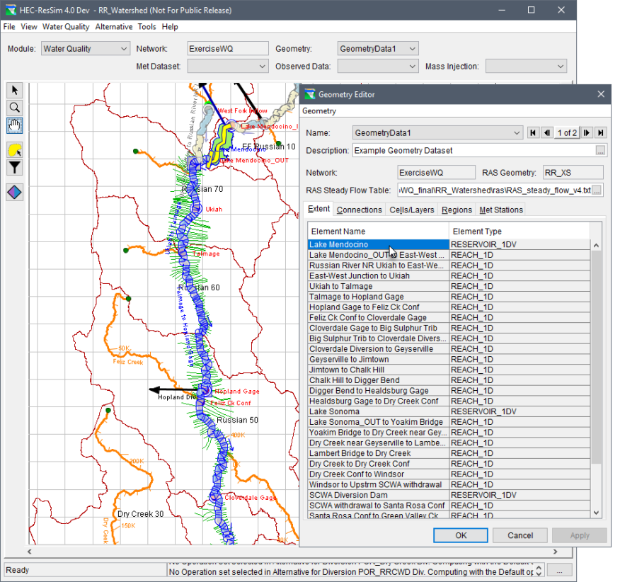
A useful ability of the Geometry Editor (Figure 4.14) is that if a network element is selected from the Element Name column (e.g., Lake Mendocino in Figure 4.18), then from the HEC-ResSim main window (Figure 4.18), the selected element is highlighted and zoomed to in the map window schematic display area (e.g., Lake Mendocino is highlighted in yellow in Figure 4.18). This ability is useful when editing the geometry extent, as described in Section 4.5.1.
Figure 4.17 – Geometry Editor – ExtentTab Figure 4.18 – HEC-ResSim Main Window – Geometry Editor – Extent Tab – Element Selection