Download PDF
Download page Layouts.
Layouts
Layouts can be made anew or imported from other EFMSim projects after the study area is created. There are two primary interfaces associated with layouts – Layout Maps and Layer Selections. Layout Maps have four menus, Layouts, Maps, Diagnostics, and Elements (Figure).

Figure. Menus of the Layout Map window.
The Layouts menu allows users to create new layouts, open existing layouts in the active layout map window, save the layout currently open in the layout map window as a different layout, rename the layout currently open in the layout map window, and delete layouts. The Layouts – New Layout Window menu option can be used to open an additional Layout Map window. Multiple map windows can be open at the same time. Selecting the Layouts – Import menu opens a three-step wizard that allows users to select the source project file, select the layouts to import, and import the selected layouts. Export Layout and Export Study Area menu options allows export of the layout currently open in the layout map window and the study area as shape files, respectively (Figure).

Figure. Layouts can be imported from existing EFMSim projects.
The Maps menu allows users to add map layers that will be associated with the layout currently open in the layout map window.
The Diagnostics menu has options named Element Size, Centroid, and Time and Memory. Selecting each option opens a new tab within the current Layout Map window. The Element Size tab is intended to help users work with very small elements created when drawing elements or when filling elements with smaller elements. Elements are filtered per size range and can be selected and merged with neighboring elements. The Centroid tab identifies elements whose centroids falls outside of their element area, which can then be relocated to fall within their element areas. The Time and Memory tab is informational. It allows the user to enter details about their application and estimate compute times and memory requirements.
Selecting the Layouts – Elements menu option opens a three-step wizard that allows users to pick whether to import elements from an existing layout or an external data layer, selecting the layout or data layer, and then selecting features to be imported as new elements.
Layouts are collections of elements that wholly fill the study area. When a new layout is created, it is automatically populated with one element. Additional elements can be imported via the Layouts – Elements menu or made by the user in a variety of ways, including using button-based features of the layout map windows (Figure).
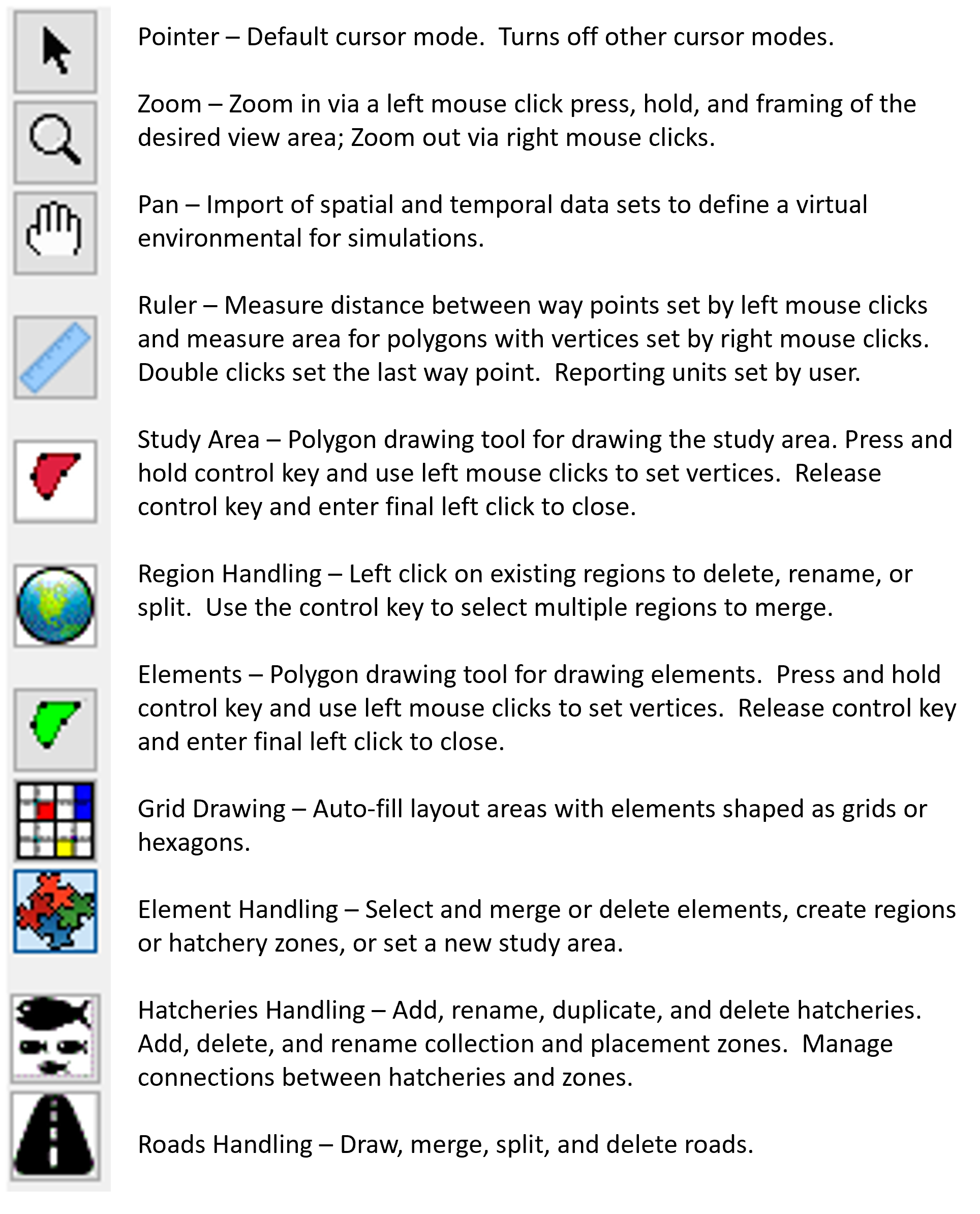
Figure. Purpose and function of Layout Map window buttons.
The Polygon Trace button (green-filled polygon icon; the cursor changes to a “+”), press and hold the control key, use left mouse clicks to enter element boundary vertices, release the control key and use a final left mouse click to add the final vertex, which is connected to the first vertex to close the element polygon.
The Grid Drawing button allows the user to select one or more elements to be filled with other elements (multiple elements are selected by pressing and holding the control key and using left mouse clicks to select and deselect individual elements). When the selection is made, right clicking on the selected area will offer a menu option called Fill that opens a window with options to fill with grid and fill with hexagons per user specified sizes and anchor points. If no selection is made, right clicking will offer a menu option called Draw that can be used to place a grid of elements at either the location of the right mouse click or a user-specified latitude and longitude.
The Element Handling button allows the user to select one or more elements and then edit details, delete, merge, set as study area polygon, create a region, or create a hatchery zone. Elements can be selected by framing an area with clicking and holding the left mouse button and dragging the frame to the desired extent. Any element that intersects with the frame will be selected. Elements can also be selected by pressing and holding the shift key and then clicking and holding the left mouse button to lasso desired elements. Pressing and holding the control key enables left mouse clicks to select and deselect individual elements. As voids in layouts are not allowed, deleting elements functions like a merge with the boundaries of elements selected for deletion simply removed and associated areas assimilated into remaining elements.
The Layer Selection window lists information associated with the focal Layout Map Window, including Human, Elements, Regions, Study Area, and any GIS layers associated with the layout open in the focal Layout Map Window, including basemaps, map layers, and aerial imagery (Figure). The four default items (Human, Elements, Regions, and Study Area) apply to all layouts. The Human item is generally for human influences that affect ecosystems and currently includes subitems for Hatcheries and Roads. The Elements item has symbology for elements. The Study Area item has symbology for the study area and boundary conditions. The Regions item has symbology for new regions maps and existing regions maps. It also has a series of right click menus that allow regions maps to be added, imported, renamed, and deleted and that allow regions to be imported, renamed, and deleted.
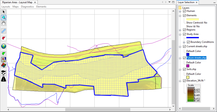
Figure. The Layer Selection window lists information associated with the focal Layout Map window.
Again and importantly, the Layer Selection window list is associated with the focal Layout Map Window. This means that the list reflects the Layout Map window most recently clicked by the user. If multiple Layout Map windows are open, the Layer Selection list will update as the user clicks from one map window to another. List, list order, and map layers are specific to the parent layout. Default items, base maps, and aerial imagery are global for all layouts. List order and appearance are managed by clicking on items in the list and using right click menu options for Expand, Collapse, Move To Top, Move up, Move Down, and Move To Bottom. List order has two parts. The default items are reordered amongst themselves and are always listed above base maps, map layers, and aerial imagery. Similarly, base maps, map layers, and aerial imagery can be reordered amongst themselves and are always listed below the default items. For example, a Move to Bottom command for the Elements item will move it to the bottom of the default items, but still above any map layers.