Create a Warning Issuance Scenario
To create a warning issuance scenario:
- From the Study Tree, which is in the Study Pane, right-click Warning Issuance Scenario, from the shortcut menu click New. The New Warning Issuance Scenario dialog box opens.
- Enter a name in the Name box, an optional description can be provided in the Description box.
- Click the radio button to select the warning type. Warnings can be issued either by Warn Relative to Start Time (default) or Warn By Rule. The New Warning Issuance Scenario dialog box changes dependent upon which warning type is selected.
Once a selection is made for how the warning is triggered, a selection has to be made for where the warning is broadcast. In the Define Time By dropdown menu one of two options can be selected All Structures (default), or by Warning Region.

Figure: New Warning Issuance Scenario Dialog Box
- Once the warning issuance scenario has been defined, click OK. The New Warning Issuance Scenario dialog box (above figure) closes, and the newly defined warning issuance scenario appears in the Study Tree, under the Warning Issuance Scenario folder.
Warn Relative to Start Time
Warning relative to start time issues a warning that is a fixed number of hours relative to the start time of the simulation regardless of the event being modeled, or the type of inundation configuration. This option is designed to support Grids Only inundation configurations (review Inundation Data), where no logical physical trigger exists in the data. Typically, warning occurs relative to the initiation of a breach condition in the hydraulic model. Through coordination between an HEC-FIA modeler and a hydraulic modeler, a breach condition can be defined relative to the start of the simulation. Arrival time grids are defined relative to the start time. Thus an arrival time of zero signifies arrival of water at the beginning of the specified time window. If the hydraulic modeler generates an arrival grid such that the first time in the grid is the breach time, every cell that was wet before the breach maps to zero.
Note: Warning time can cause issues if there are a significant number of structures in the floodplain that are in the cells that were wet before breach. Therefore, it is very important that the hydraulic modeler and the HEC-FIA modeler coordinate. However, if the warning issuance relative to start time is also set at zero, the warning goes out on the first time step of the HEC-FIA simulation. If the user sets the warning issuance to be -30, the warning goes out 30 minutes before the simulation start, which would be equivalent to 30 minutes before breach.
When using gridded hydraulic data, the time in the HEC-FIA time window does not have to be the same as the simulation time in HEC-RAS, but the relative timing must be preserved. When using HEC-DSS time series hydraulic data, the times in the time window must be within the times in the HEC-DSS time series.
Define Time By: All Structures
When the warning issuance time is defined by All Structures, the same warning time is applied to all structures. Applying the same warning time to all structures is useful when a rough estimate is desired but this scenario is also generally a poor representation of reality.
In the Hours Relative to Start Time column, the user defines the hours between the Start Time identified in the Time Window and the issuance of the warning. Numbers for hours relative to start time can be entered in decimals such that 1.5 is equivalent to 1 hour and 30 minutes after the start time and -0.25 would be 15 minutes before the start of the simulation.
From the Error Distribution Type list there are five choices: None, Normal, Log Normal, Triangular, and Uniform. The choice of the error distribution makes the last four columns in the table editable or non-editable for the following columns: Standard Deviation, Log10 Stand Deviation, Minimum Value, and Maximum Value. An offset (in minutes) is entered in the Most Likely Offset column.
Define Time By: Warning Region
Defining the warning issuance time by Warning Region allows the user to use a polygon shapefile to define which rule or what time the warning issuance occurs within each polygon in the polygon shapefile.
- From the New Warning Issuance Scenario dialog box, from the Define Time By list, select Warning Region and the New Warning Issuance Scenario dialog box updates.
- From the Warning Region list select the appropriate polygon shapefile (e.g., EPZ.shp). Note, if the list of shapefiles in the dropdown menu does not contain the desired shapefile, then the user must add the shapefile to the HEC-FIA project as map layer.
The selected shapefile contains a unique name field that contains the warning regions. From the Attribute list, select the appropriate field name (e.g., Name)), and the table updates. The table on the New Warning Issuance Scenario dialog box now has a row for each polygon contained in the shapefile (a multi-part polygon should only have one record in the table). As described in the All Structures section, the user provides information for the remainder of the table.

Figure: New Warning Issuance Scenario Dialog Box - Define Time By Warning Region Option
Warn By Rule
Warning by rule is an option that allows users to input stage based warning issuance rules. For instance, the user may specify that a warning is issued whenever the river stage exceeds a flood stage at a gage of interest in the study area. The specified rules depend upon the dynamics of the study area and its hydraulic characteristics. This option can only be utilized for inundation configurations that are either Cross Sections Only or Grids and Cross Sections (review Inundation Data Section).
From the New Warning Issuance Scenario dialog box select Warn by Rule, the New Warning Issuance Scenario dialog box changes. To define rules proceed with the following steps:
From the Inundation Configuration list, select the inundation configuration that is intended to be used for this warning issuance scenario. Rules can only be defined at locations where a HEC-DSS time series hydrograph is present, so only inundation configurations that contain cross sections can be used for rule based warnings.
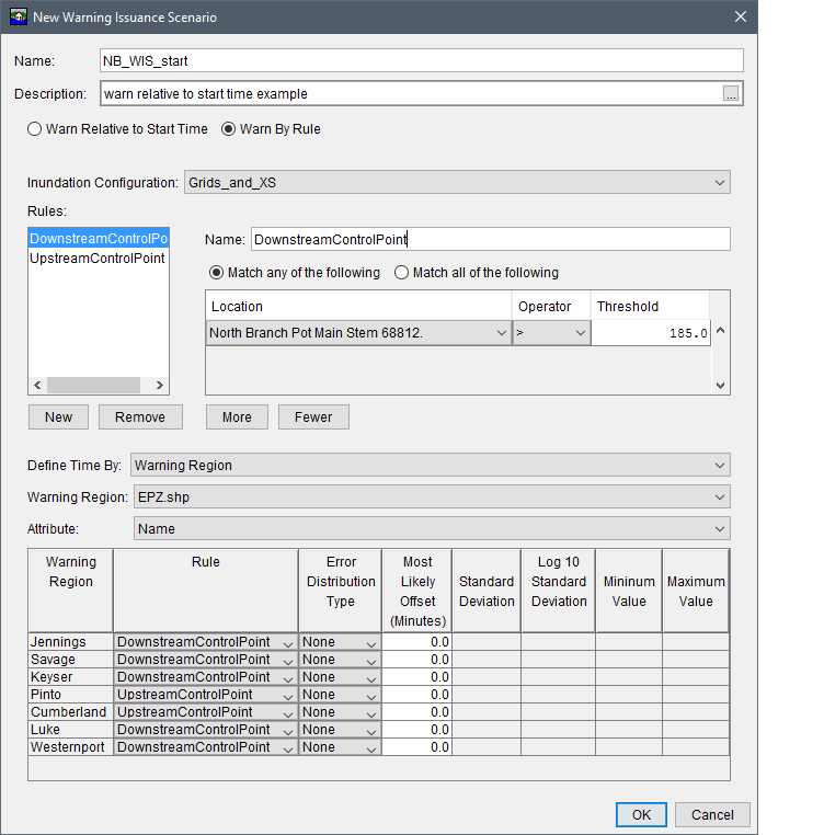
Figure: New Warning Issuance Scenario Dialog Box - Warn By Rule
- Click the New button, this creates a new rule and provides a default name in the Name box. The Name box is editable so the user can change the name to a more meaningful name (e.g., DownstreamControlPoint).
- There are two options for how the rule is executed, click the radio button to select:
-Match any of the following is an OR logical statement. An example would be: "if condition one is met OR condition two is met, then the warning has been triggered".
-Match all of the following is an AND logical statement. An example would be: "if condition one is met AND condition two is met, then the warning has been triggered". - Once the user has made a selection on how the rule is executed, click the More button to add a Location, Operator and Threshold to the table. A Location is a specific cross section. This provides HEC-FIA with information to know which hydrograph to use (a record in a HEC-DSS file), so that the condition can be tracked.
An Operator is an expression symbol which defines how to evaluate the condition. For instance if the user chooses the "=" operator, the warning is only initiated when stage is exactly equal to the threshold. If the user uses the operator ">", the warning is issued as soon as the hydrograph exceeds the threshold value; if the first time step of the hydrograph is greater than the threshold, the warning goes out on the first time step.
A Threshold is a value that is used to compare to the hydrograph based on the operator symbol. Be sure to define the threshold in the same units and type as the hydrograph data supplied at the location. - Create and define additional rules by repeating Steps 2 through 4. Once the rules are defined, specify the geographic extent and the offset time using the Define Time By options outline above.
Incorporating Uncertainty
Many factors may influence when a warning is actually issued. In HEC-FIA, the user is able to define uncertainty about the warning issuance. However, the components of this uncertainty are lumped into a single distribution. Example scenarios contributing to this lumped sum uncertainty distribution include: the chance that a warning is issued in anticipation of a particular condition being met; the chance that a warning is not issued because it occurs without anyone being aware; or the chance that the warning is delayed due to decision making processes at the Emergency Management Agency; or delays due to the time between identification of the natural event and notifying the Emergency Management Agency of disaster potential.
To define uncertainty on a warning issuance:
- Following the Define Time By selection (which can be either option), the first step is to select a distribution type, from the New Warning Issuance Scenario dialog box. From the Error Distribution Type column in the table, select the error distribution type from the available list. The available types are Normal, Log Normal, Triangular, and Uniform.
- Each Error Distribution Type has different values which are required to define the entire distribution, but there are a few things to note when filling out the parameters:
- The values of the uncertainty distribution parameters are in minutes, not hours.
- The values of the uncertainty distribution parameters are relative to the time defined in the second column of the table. (Hours relative to start or when the rule is executed for the specific event.)
The uncertainty values are added to the value in the second column of the table, thus negative values make the warning go out earlier, and positive values make the warning issuance happen later.
Figure: New Warning Issuance Scenario Dialog Box - Warning Uncertainty
During a Monte Carlo compute, a random number is selected for each row in the table, and a warning issuance time is calculated for each structure depending on the geo-location of the structure for Warning Region or All Structures.