Coordinate System Types
A coordinate system is a method of representing points in a space of given dimensions by coordinates. Two coordinate system types of interest to FIA are the geographic coordinate system, which is based on latitude and longitude coordinates, and the project coordinate system, which represents the projection of a geographic coordinate system on a plane.
The simplest way to add a coordinate system to an HEC-FIA project is to import a projected shapefile into the map window. The coordinates are set based on the *.prj file of the first map added to the map window.
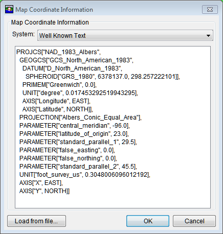
Another way to add a coordinate system to an HEC-FIA project is from the Default Map Properties for dialog box, click View. The Map Coordinate Information dialog box opens.

Figure: Coordinate Information Dialog Box
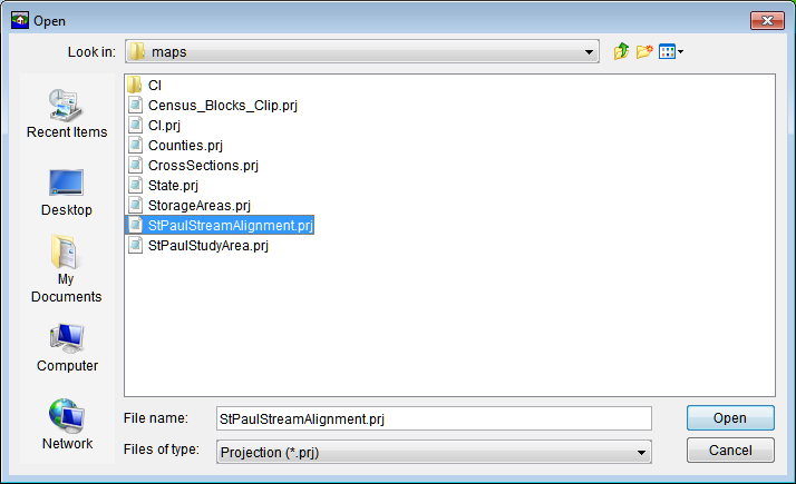
Click Load from file, an Open Browser opens, browse to a .prj that contains the correct projection for the HEC-FIA project.

Figure: Open Browser
A few notes on performance, if a background image file or an internet map file is being used, it is best to set the projection to that of the background image map, this speeds up the zooming by re-projecting the data on the fly rather than the background image. Also, the background imagery is better when viewed in the native projection.
The coordinate systems available in HEC-FIA are shown in Table C.1. This table also shows the units and spheroid type for each coordinate system. A spheroid (ellipsoid) is the shape of the earth that used in the calculations that transform positions on the curved surface of the earth to positions on a flat map. It is part of the horizontal datum, which approximates the curved surface of the earth over part of the globe.
Table: Coordinate Systems Available in HEC-FIA
Coordinate Systems | Units | Spheroid |
X-Y | U.S. feet | N/A |
Google/Bing Web Mercator | WGS 84 | |
Geographic | radians | WGS 72 |
Universal Transverse Mercator | meters | GRS 1980(NAD83) |
State Plane Coordinates | meters | GRS 1980(NAD83) |
Albers Equal-Area Conic | Degrees of Arc | Sphere of Radius 6370997 meters |
Lambert Conformal Conic | International Feet | |
Transverse Mercator | U.S. feet | Clarke 1866(NAD27) |
Albers Equal-Area Conic (SHG) | meters | GRS 1980(NAD83) |
Polar Stereographic (HRAP) | meters | Sphere of Radius 6371200 meters |
X-Y Coordinate System
The X-Y coordinate system is also known as the World Coordinate System (WCS). This superimposes a grid on layer features to establish x- and y-coordinates for each point on the layer. The origin point (0,0) can be located anywhere, but every object is located in relation to the origin point. The X-Y coordinate system has no spheroid specification.
To set parameters for the X-Y Coordinate System:
- From the Maps menu, click Default Map Properties. The Default Map Properties for dialog box opens.
The Coordinate System field displays the name of the selected coordinate system (X-Y is default). Click View. The Map Coordinate Information dialog box opens.

Figure: Map Coordinate Information Dialog Box - X-Y Coordinate System
- From the System list, select X-Y.
- From the Units list, select the units for the X-Y coordinate system.
- Click OK. The Map Coordinate Information dialog box closes. In the Coordinate System box of the Default Map Properties for dialog box, X-Y is displayed.
Google/Bing Web Mercator Coordinate System
The Google/Bing Web Mercator coordinate system is a variation of the Mercator projection and is the standard for most web mapping applications. Also, used by Bing and OpenStreet.
From the Maps menu, click Default Map Properties. The Default Map Properties for dialog box opens.

Figure: Map Coordinate Information Dialog Box Google Bing Web Mercator Coordinate System
- The Coordinate System box displays the name of the selected coordinate system (X-Y is default). Click View. The Map Coordinate Information dialog box opens.
- From the System list, select Google/Bing Web Mercator.
- The Map Coordinate Information dialog box displays information about the coordinate system.
- Click OK. The Map Coordinate Information dialog box closes. In the Coordinate System box of the Default Map Properties for dialog box, Google/Bing Web Mercator should be displayed.
Geographic Coordinate System
Each of the different coordinate systems has their own set of options editable in the Map Coordinate Information dialog box (Figure C.7). For a Geographic Coordinate System, users can define units and spheroid.

Figure: Map Coordinate Information Dialog Box - Geographic Coordinate System
To set parameters for the Geographic Coordinate System:
- From the Maps menu, click Default Map Properties. The Default Map Properties for dialog box opens.
- The Coordinate System field displays the name of the selected coordinate system (X-Y is default). Click View. The Map Coordinate Information dialog box opens.
- From the System list, select Geographic.
- From the Units list, select the units for the Geographic coordinate system. The only units available should be Radians, Degrees of Arc, and Seconds of Arc.
- From the Spheroid list, select a spheroid type for the Geographic coordinate system.
- Click OK. The Map Coordinate Information dialog box closes. In the Coordinate System box of the Default Map Properties for dialog box, Geographic should be displayed.
Universal Transverse Mercator Coordinate System
The Universal Transverse Mercator (UTM) coordinate system is a projection coordinate system. UTM is used to define horizontal positions throughout the world by dividing the surface of the Earth into six-degree zones, with a central meridian in the center of each zone.
To set parameters for the Universal Transverse Mercator Coordinate System:
- From the Maps menu, click Default Map Properties. The Default Map Properties for dialog box opens.
The Coordinate System field displays the name of the selected coordinate system (X-Y is default). Click View. The Map Coordinate Information dialog box opens.

Figure: Map Coordinate Information Dialog Box - Universal Transverse Mercator Coordinate System
- From the System list, select Universal Transverse Mercator.
- From the Units list, select the units for the Universal Transverse Mercator coordinate system.
- From the Spheroid list, select a spheroid type for the Universal Transverse Mercator coordinate system.
- In the UTM Zone box, enter the UTM zone number.
- Click OK. The Map Coordinate Information dialog box closes. In the Coordinate System box of the Default Map Properties for dialog box, Universal Transverse Mercator should be displayed.
State Plane Coordinate System
The State Plane Coordinate System (SPCS) was established in the 1930's and now covers all fifty states. Zones were established for each state using either the Lambert Conformal or Traverse Mercator projections. Units are generally in feet (NAD27) or meters (NAD83).
To set parameters for the State Plane Coordinate System:
- From the Maps menu, click Default Map Properties. The Default Map Properties for dialog box opens.
The Coordinate System field displays the name of the selected coordinate system (X-Y is default). Click View. The Map Coordinate Information dialog box opens.

Figure: Map Coordinate Information Dialog Box - State Plane Coordinates Coordinate System
- From the System list, select State Plane Coordinates.
- In the Zone box, enter the zone for the state. These codes are FIPS codes.
- Click OK. The Map Coordinate Information dialog box closes. In the Coordinate System box of the Default Map Properties for dialog box, State Plane Coordinates should be displayed.
Albers Equal-Area Conic Coordinate System
The Albers Equal-Area Conic projection was established for mapping large areas. The projection is an equivalent projection, where areas are proportional and directions are true in limited areas.
To set parameters for the Albers Equal-Area Conic Coordinate System:
- From the Maps menu, click Default Map Properties. The Default Map Properties for dialog box opens.
- The Coordinate System field displays the name of the selected coordinate system (X-Y is default). Click View. The Map Coordinate Information dialog box opens.
From the System list, select Albers Equal-Area Conic.

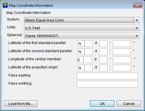
Figure: Map Coordinate Information Dialog Box - Albers Equal-Area Conic Coordinate System
- From the Units list, select the units for the Albers Equal-Area Conic coordinate system.
- From the Spheroid list (Figure C.10), select a spheroid type for the Albers Equal-Area Conic coordinate system.
- The remaining items to be entered are the angular parameters that are required to fine-tune the projection. When specifying latitudes enter N or S, and for longitudes, enter E or W. Use the SPACEBAR to toggle between the entries.
- Click OK. The Map Coordinate Information dialog box closes. In the Coordinate System box of the Default Map Properties for dialog box, Albers Equal-Area Conic should be displayed.
Lambert Conformal Conic Coordinate System
The Lambert Conformal Conic projection is used extensively for mapping areas of the world with predominantly east-west orientation. Similar to the Albers Equal-Conic projection, however the projection is not done in an equal-area.
To set parameters for the Lambert Conformal Conic Coordinate System:
- From the Maps menu, click Default Map Properties. The Default Map Properties for dialog box opens.
The Coordinate System field displays the name of the selected coordinate system (X-Y is default). Click View. The Map Coordinate Information dialog box opens.

Figure: Map Coordinate Information Dialog Box - Lambert Conformal Conic Coordinate System
3.From the System list, select Lambert Conformal Conic.
4.From the Units list, select the units for the Lambert Conformal Conic coordinate system.
5.From the Spheroid list, select a spheroid type for the Lambert Conformal Conic coordinate system.
6.When specifying latitudes enter N or S, and for longitudes, enter E or W. Use the SPACEBAR to toggle between the entries.
7. Click OK. The Map Coordinate Information dialog box closes. In the Coordinate System box of the Default Map Properties for dialog box, Lambert Conformal Conic should be displayed.
Transverse Mercator Coordinate System
In the Transverse Mercator projection, a sphere is projected onto a cylinder tangent to a central meridian. It is similar to the Lambert Conformal Conic project, but used to portray large areas in a north-south orientation. Many national grid systems are based on the Transverse Mercator projection.
To set parameters for the Transverse Mercator Coordinate System:
- From the Maps menu, click Default Map Properties. The Default Map Properties for dialog box opens.
The Coordinate System field displays the name of the selected coordinate system (X-Y is default). Click View. The Map Coordinate Information dialog box opens.

Figure: Map Coordinate Information Dialog Box - Transverse Mercator Coordinate System
- From the System list, select Transverse Mercator.
- From the Units list, select the units for the Transverse Mercator coordinate system.
- From the Spheroid list, select a spheroid type for the Transverse Mercator coordinate system.
- Enter a scaling factor for central meridian, in the Scale factor at central meridian box.
- When specifying latitudes enter N or S, and for longitudes, enter E or W. Use the SPACEBAR to toggle between the entries.
- Click OK. The Map Coordinate Information dialog box closes. In the Coordinate System box of the Default Map Properties for dialog box, Transverse Mercator should be displayed.
Albers Equal-Area Conic (SHG) Coordinate System
The standard hydrologic grid (SHG) is a variable-resolution square-celled map grid defined for the conterminous United States, based on the Albers Equal-Area Conic projection system. The parameters are set to match USACE map coordinates for SHG.
To view the parameters for the Albers Equal-Area Conic (SHG) Coordinate System:
- From the Maps menu, select Default Map Properties. The Default Map Properties for dialog box opens.
The Coordinate System field displays the name of the selected coordinate system (X-Y is default). Click View. The Map Coordinate Information dialog box opens.

Figure: Map Coordinate Information Dialog Box - Albers Equal-Area Conic (SHG) Coordinate System
3.From the System list, select Albers Equal-Area Conic (SHG).
4.From the Units list, select the units for the Albers Equal-Area Conic (SHG) coordinate system.
5.From the Spheroid list, select a spheroid type for the Albers Equal-Area Conic (SHG) coordinate system.
6.The remaining parameters are informational and are not editable.
7. Click OK. The Map Coordinate Information dialog box closes. In the Coordinate System box of the Default Map Properties for dialog box, Albers Equal-Area Conic (SHG) should be displayed.
Polar Stereographic (HRAP) Coordinate System
The Hydrologic Rainfall Analysis Project (HRAP) projection system, is a type of polar stereographic coordinate system. The parameters are set to match NWS map coordinates used for radar grids.
To view the parameters for the Polar Stereographic (HRAP) Coordinate System:
- From the Maps menu, click Default Map Properties. The Default Map Properties for dialog box opens.
- The Coordinate System field displays the name of the selected coordinate system (X-Y is default). Click View. The Map Coordinate Information dialog box opens.
- From the System list, select Polar Stereographic (HRAP).
- From the Units list, select the units for the Polar Stereographic (HRAP) coordinate system.
- From the Spheroid list, select a spheroid type for the Polar Stereographic (HRAP) coordinate system.
- The values entered in the Semi-major and Semi-minor boxes reflect the length of the axes of an ellipse and change according to spheroid selection. In the figure below, Sphere of Radius 6371200 Meters is selected as the spheroid, and the lengths of the axes have been automatically entered to reflect a sphere of radius 6371200 feet.
- The remaining parameters are informational and are not editable.
Click OK. The Map Coordinate Information dialog box closes. In the Coordinate System box of the Default Map Properties for dialog box, Polar Stereographic (HRAP) should be displayed.

Figure: Map Coordinate Information Dialog Box - Polar Stereographic (HRAP) Coordinate System