Download PDF
Download page Formatting gSSURGO Data for Use within HEC-HMS.
Formatting gSSURGO Data for Use within HEC-HMS
Last Modified: 2022-10-25 14:11:01.589
The underlying principle for this walkthrough is that surficial texture estimates are used from the gSSURGO databases to estimate model parameters and not the estimates of Ksat, porosity, field capacity, etc that are included in the database. All required HEC-HMS parameters are related back to surficial soil textures using literature values and should be treated as initial estimates. This is the same for all sources of similar data including Engineer Manual 1110-2-1417 Flood-Runoff Analysis and the HEC-HMS Technical Reference Manual. Regardless of the source, these initial estimates must be calibrated and validated.
- Begin by downloading gSSURGO data for the area of interest here.
- gSSURGO data is distributed by state.
- Depending upon the size or location of the area of interest, you may need to download more than one gSSURGO database.
- After downloading and extracting the geodatabase(s), using ArcGIS, navigate within the geodatabase and add the MUPOLYGON layer, as shown in the following image.
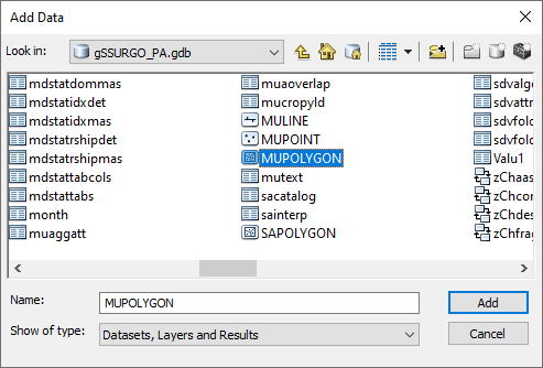
- This step, as well as the following steps, will need to be completed for each state (if your area of interest overlaps state boundaries).
The MUPOLYGON layer(s) can be optionally clipped to a smaller area of interest to reduce processing times, as shown in the following image.
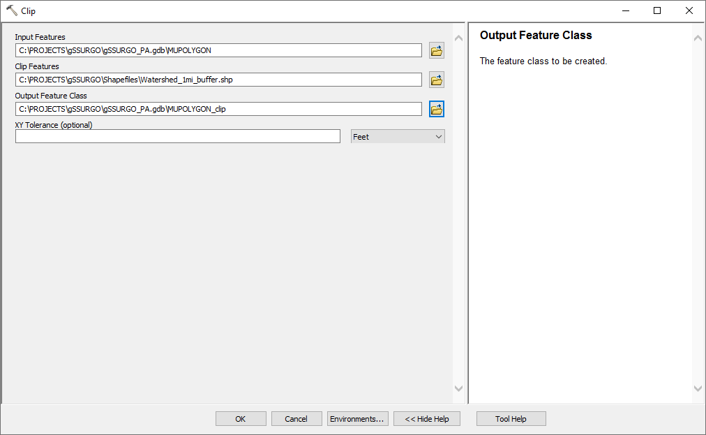
- Add columns to the MUPOLYGON layer attribute table that correspond to the required parameters based upon the chosen infiltration routine.
- In this example, parameters corresponding to the Green Ampt loss method are required. Therefore, five columns were added to the attribute table corresponding to:
- Texture – text string w/ 150 character limit
- Srf_Text – text string w/ 150 character limit
- Ksat – float w/ default precision/scale
- WF_Suct – float w/ default precision/scale
- ePorosity – float w/ default precision/scale
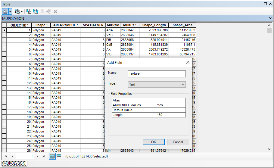
- In this example, parameters corresponding to the Green Ampt loss method are required. Therefore, five columns were added to the attribute table corresponding to:
- Load multiple tables from the gSSURGO database to ArcGIS:
- mapunit
- component
- chorizon
- chtexturegrp
- chtexture
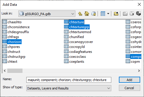
- Join tables to the MUPOLYGON layer using the attribute keys contained within that table below.
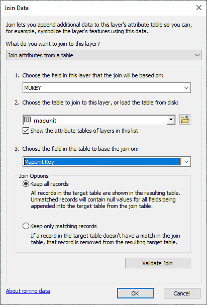
For example, information in the mapunit table is joined to the MUPOLYGON layer using the attribute MUKEY in the MUPOLYGON layer and the attribute mapunit key in the mapunit table.
You must click on the drop down menu in item #2 and select the appropriate table even if it is selected by default. The process will not work without performing this step.
Parent/Child Join RelationshipsParent
Child
Join Field
MUPOLYGON
mapunit
MUKEY / mapunit key
mapunit
component
mapunit key
component
chorizon
component key
chorizon
chtexturegroup
chorizon key
chtexturegroup
chtexture
chtexturegroup key
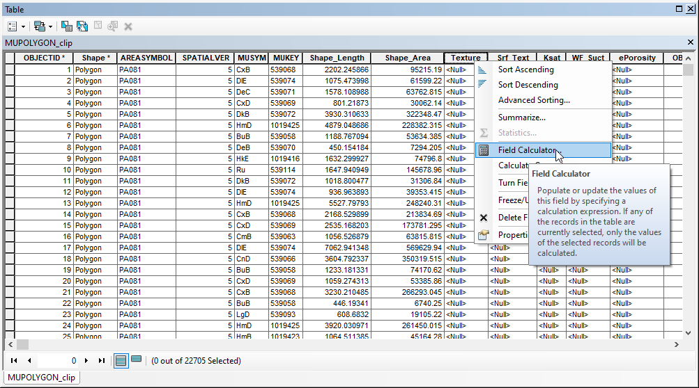
- Within the MUPOLYGON attribute table, right click on the Texture column header and select Field Calculator, as shown in the figure below.
Select the [chtexturegrp.texdesc] record, as shown in the following figure.
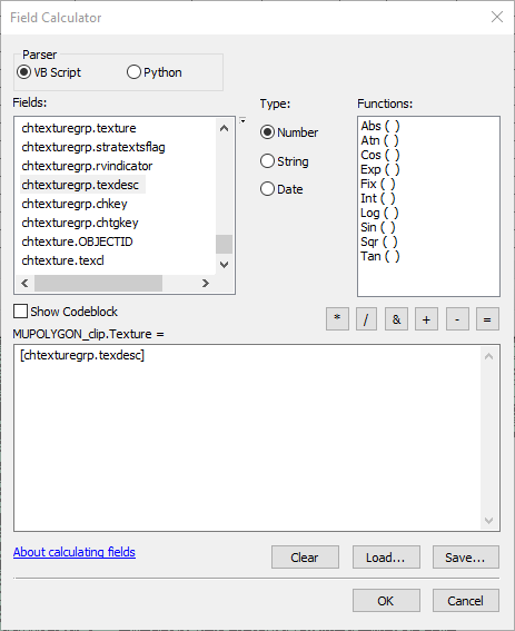
Warnings may be generated noting that the results may be greater than the capacity of the data container/attribute column. Click Yes to proceed.
This may take a while depending upon the size of the dataset in question.
- The Texture column should now be populated with values. However, not all polygons will have values.
- Select all polygons that have <null> Texture values. Use the Select by Attributes tool, as shown in the following figure:
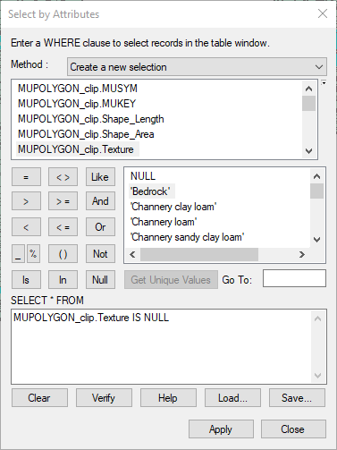
- Use Field Calculator to fill in the blank values. Use the [mapunit.muname] field as the argument, as shown in the following figure.
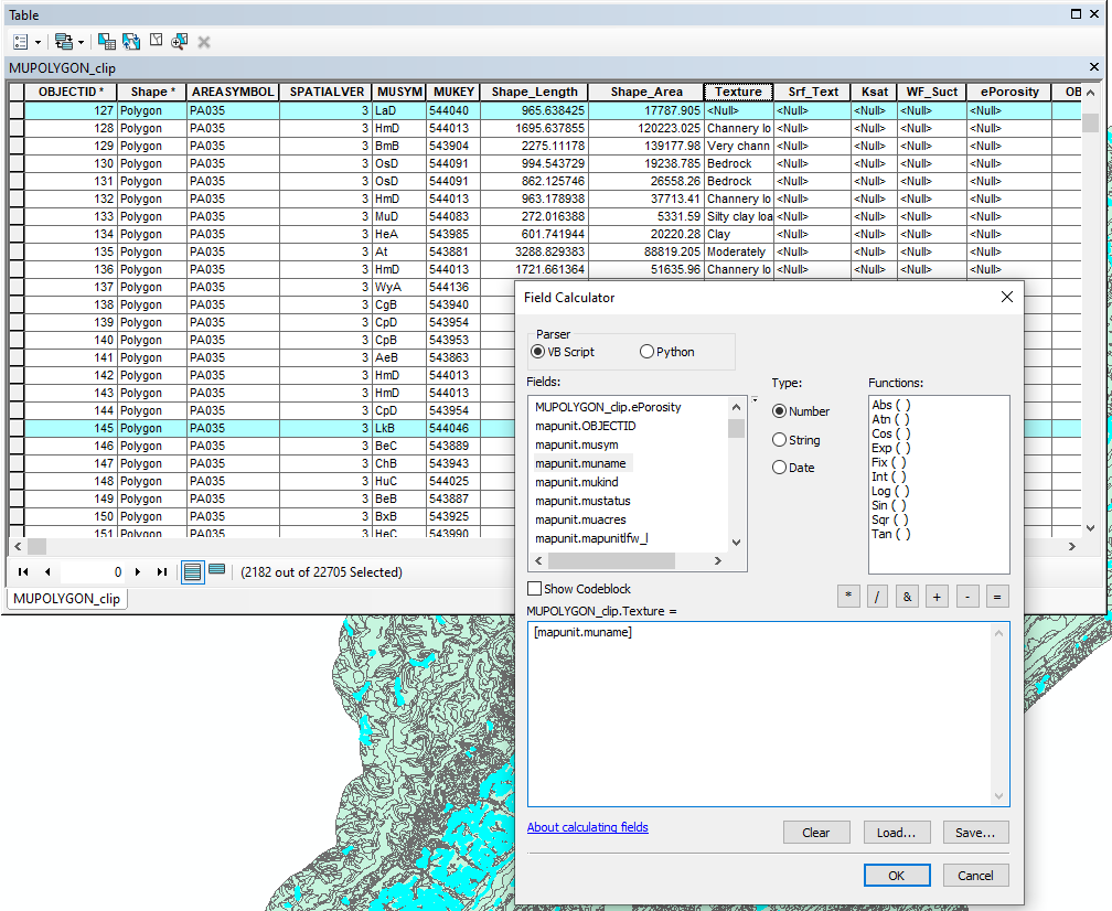
- Select all polygons that have <null> Texture values. Use the Select by Attributes tool, as shown in the following figure:
- Some Textures may not be easily relatable to literature values of textures. These will require manual alterations.
- For instance, it is not clear what values should be associated with Textures like Pits, Gravel, or Fluvaquents.
- Make changes that are needed and within the Srf_Text column. This way, there is both an original (Texture) and modified (Srf_Text) column within the MUPOLYGON attribute table.
Users can make use of applications like Microsoft Excel to sort, remove duplicates, and associate the required infiltration parameters to the given soil texture using lookup functions and literature values.
However, as of Microsoft Office 2013, users can no longer save .dbf files within any Microsoft Office applications. If you wish to perform this step outside of ArcGIS, contact HEC for a database file editing application.
Use published literature values, like those shown below (reproduced from Rawls, Brakensiek, and Miller, 1983) to define the required parameters for each soil texture
Soil Textures and Effective Porosity, Wetting Front Suction Head, and Saturated Hydraulic ConductivityTexture
Saturated Hydraulic Conductivity (in/hr)
Wetting Front Suction Head
(in)Effective Porosity
(in3/in3)Clay
0.01 12.5 0.39 Clay Loam
0.04 8.2 0.31 Loam
0.1 3.5 0.43 Loamy Sand
1.2 2.4 0.40 Sand
4.6 1.9 0.42 Sandy Clay
0.02 9.4 0.32 Sandy Clay Loam
0.06 8.6 0.33 Sandy Loam
0.4 4.3 0.41 Silt Loam
0.3 6.6 0.49 Silty Clay
0.02 11.5 0.42 Silty Clay Loam
0.04 10.7 0.43 Displaying resulting soil textures, Ksat, Porosity, etc show that results can vary by more than just soil texture. For instance, political boundaries can be seen within the subsequent GIS information, as shown in the following image.
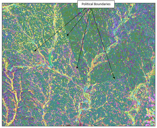
If the same soil scientist analyzed the whole area, results would be much more "normal". However, different soil scientists were used throughout the modeling domain.Keep in mind that these are INITIAL estimates and parameters must be calibrated.
- Once initial parameter values have been assigned to the soil polygons, use the Merge (Data Management) tool within ArcGIS to create a final, seamless soil dataset for your area of interest.
- GeoTIF rasters can then be created from the polygon coverage using tools within ArcGIS, as shown within the following image.
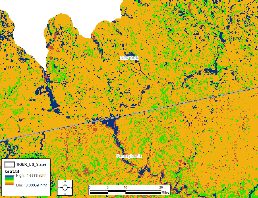
- GeoTIF rasters can be imported to HEC-HMS and used to extract loss parameters. See this tutorial for more information: Estimating Parameters with GIS Datasets.