Download PDF
Download page Introduction to the Channel Routing Tutorials.
Introduction to the Channel Routing Tutorials
Open Channel Flow
As runoff from subbasin elements arrive at defined channels, depths increase and the predominant flow regime begins to transition to open channel flow. At this point, open channel flow approximations are used to represent translation and attenuation effects as flood waves move downgradient. Each of the channel routing methods within HEC-HMS implements a hydrologic routing methodology as compared to a hydraulic approach that implements the unsteady flow equations. Each method included in the program provides a different level of detail and not all methods are equally adept at representing a particular stream.
At the heart of each routing method included in the program are the momentum and continuity equations, which are foundational within open channel flow. The momentum and continuity equations are derived from basic principles including:
- Velocity is constant, and the water surface is horizontal across any channel section.
- All flow is gradually varied, with hydrostatic pressure prevailing at all points in the channel. Thus, vertical accelerations can be neglected.
- No lateral or secondary circulation occurs.
- Channel boundaries are fixed. Erosion and/or deposition do not alter the shape of a channel cross-section.
- Water is of uniform density, and resistance to flow can be described by empirical formulas, such as Manning's and Chezy's equation (U.S. Army Corps of Engineers, 1994).
The momentum equation accounts for forces that act on a body of water in an open channel. In simple terms, it equates the sum of gravitational forces, pressure forces, and friction forces to the product of fluid mass and acceleration. The continuity equation accounts for the volume of water in a reach of an open channel, including the volume flowing into the reach, the volume flowing out of the reach, and the volume stored in the reach. When combined, these two equations are known as the St. Venant or Dynamic Wave equations.
Although the solution of the full equations is appropriate for all (and required for many) one-dimensional channel flow problems, approximations are adequate for most hydrologic simulations. Specifically, simplifications of the momentum equation are often made that only include relevant and significant terms.
Tutorial Overview
In this workshop, you will become familiar with several channel routing methods that are available within HEC-HMS. Specifically, you will:
- Estimate initial parameter values using GIS information.
- Enter the initial parameter values within a basin model, create a simulation run, and compute the simulation.
- Calibrate the initial parameter values to achieve a better fit to provided data.
- Repeat for additional channel routing methods.
- Compare and contrast the differences between each method.
Questions will be provided throughout each tutorial.
Background
In this tutorial group, the study area is designated as the Mahoning Creek watershed upstream of the town of Punxsutawney, PA. Mahoning Creek is part of the Allegheny River Basin and is located in western Pennsylvania, as shown in Figure 1.
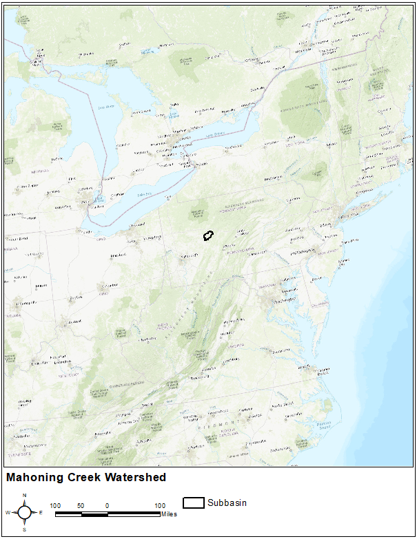
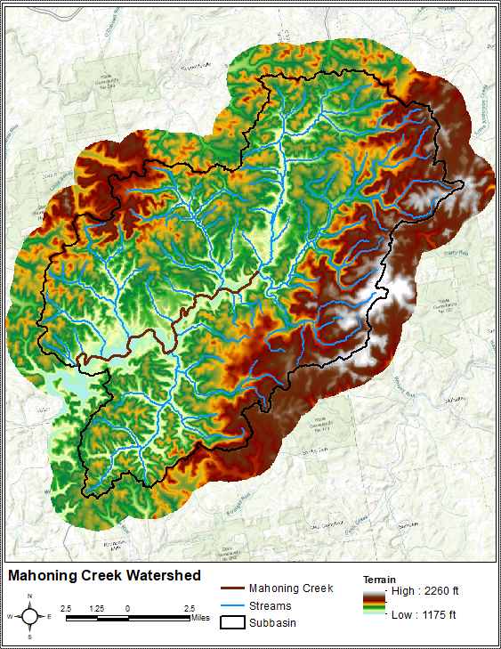
The primary conveyance system of this 158 sq. mi. study area includes the following major streams: Stump Creek, East Branch Mahoning Creek, and Mahoning Creek. The confluence of Stump Creek and East Branch Mahoning Creek is located east of the enclave of Big Run. Mahoning Creek is downstream of the confluence. Elevations within the study area range from approximately 1175 ft to 2260 ft as referenced to the North American Vertical Datum of 1988 (NAVD88), as shown in Figure 2.
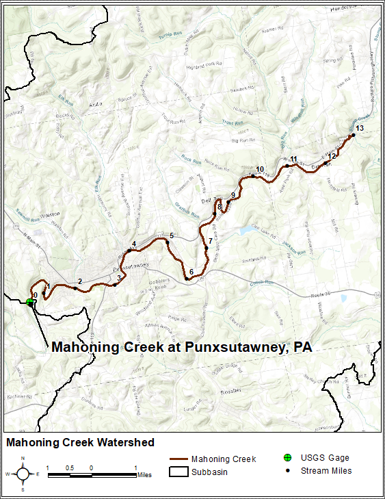
The portion of Mahoning Creek shown within Figure 3 will be used within all channel routing tutorials. This approximately 13 mile-long reach is located upstream of the U.S. Geological Survey (USGS) stream gage at Punxsutawney and downstream of the Stump Creek and East Branch Mahoning Creek confluence.
Data
A 1.5-day time period in April 1994 will be simulated within this tutorial.
Precipitation
No precipitation will be simulated within these tutorials.
Streamflow
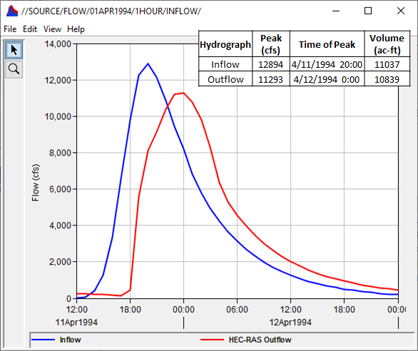
A "known" hydrograph will be used as an upstream boundary condition to the reach shown within Figure 3. All of the subsequent channel routing tutorials will route this hydrograph using various routing methods and parameterizations. This "known" hydrograph was also routed using unsteady HEC-RAS computations to develop an outflow hydrograph from the reach in question. This HEC-RAS outflow hydrograph will be used as an "observed" hydrograph with which all subsequent results will be compared. These two hydrographs are shown and detailed within Figure 4.
Model Configuration
An HEC-HMS project named "Punxsutawney_Reach_Routing" has already been created for you. This HEC-HMS project contains four basin models for Mahoning Creek (one for each reach routing method explored in this tutorial series), a meteorologic model named "NoRain", and a control specification named "April 1994". As shown within Figure 5, there is a single source element named "Inflow" that is connected to a junction named "Big Run". The "Big Run" junction is connected to a routing reach element named "Mahoning Creek" that is connected to a sink element named "Mahoning Creek Gage at Punx". These elements were originally delineated using terrain data downloaded from the USGS National Map Viewer.
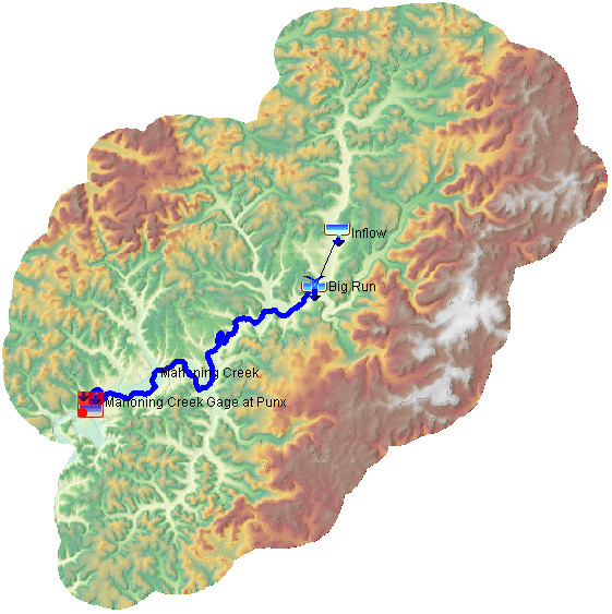
The "Inflow" source element was set to use the previously-described upstream boundary condition (i.e. "known" inflow hydrograph). The previously-mentioned HEC-RAS outflow hydrograph (i.e. "observed") was linked to the sink element.
Continue to Applying the Lag Routing Method