Download PDF
Download page Creating a New Basin Model.
Creating a New Basin Model
Last Modified: 2025-01-27 07:45:48.442
Software Version
HEC-HMS version 4.13 beta 4 was used to create this tutorial. You will need to use HEC-HMS version 4.13 beta 4, or newer, to open the project files.
Overview
In this tutorial you will create a new basin model consisting of three subbasins, two junctions, and a routing reach; then you will connect the elements to form a hydrologic network, and finally enter parameter data for these hydrologic elements.
Steps
- Open HEC-HMS.
- From the File | New menu, create a new project.
- Name the project "Punxsutawney". Set the default unit system to U.S. Customary.
- From Components on the menu bar, select the Basin Model Manager option. The Basin Model Manager window will open.
- Click the New… button to begin the process of creating a basin model. The Create A New Basin Model window will open.
- Change the default basin model name (Basin 1) to Punxsutawney and add the description Headwaters to the City of Punxsutawney - Existing Conditions.
- Click the Create button when all the information is correct. The new, empty basin model will be added to the Watershed Explorer. Close the Basin Model Manager.
- Set the default methods for subbasins and reaches that will be used when creating new elements. From the Tools menu, select the Program Settings … option.
- Select the Defaults tab and set the default loss method to Initial and Constant, the default transform method to Clark Unit Hydrograph, the default baseflow method to Linear Reservoir, and the default routing method to Lag. Click the OK button when you have finished making the selections.
- Open the basin model by clicking on it in the Watershed Explorer.
- Click the subbasin creation tool icon
 in the components toolbar.
 - Click on the basin map to create the first subbasin element. You can use the default name.
- Add two more subbasin elements.
- Switch to the reach creation tool
 and click on the basin map to create a reach element.
 - Switch to the junction creation tool
 and add two junction elements to the basin map. The elements should be placed as shown in the figure below (Use the arrow tool
  to reposition elements as needed).
Connect the elements into a hydrologic network as shown in the figure below. Right click on each element and select the Connect Downstream option. Use the mouse to identify the element that should be downstream. A connection line is drawn to show the elements are connected.

Question: In this step modeling elements are graphically connected. What is another way to connect elements?Elements can be connected from the component editor for a given element by selecting a downstream element.
- Click on the Subbasin-1 icon in the Watershed Explorer and rename it to Stump Creek.
- Similarly, click on the other subbasin elements and rename them too; Subbasin-2 becomes EB Mahoning Creek and Subbasin-3 becomes Mahoning Creek Local as shown in the figure below.


Remember to save your work often by clicking on the save icon:

Enter the area for each of the subbasins. First select the basin model, then Click on the Parameters menu and select the Subbasin Area option. Enter the area as shown in the table below
Name Area (mi2) EB Mahoning Creek 41 Stump Creek 29
Mahoning Creek Local 88 Parameters | Subbasin Area

Input the subbasin areas provided in the table above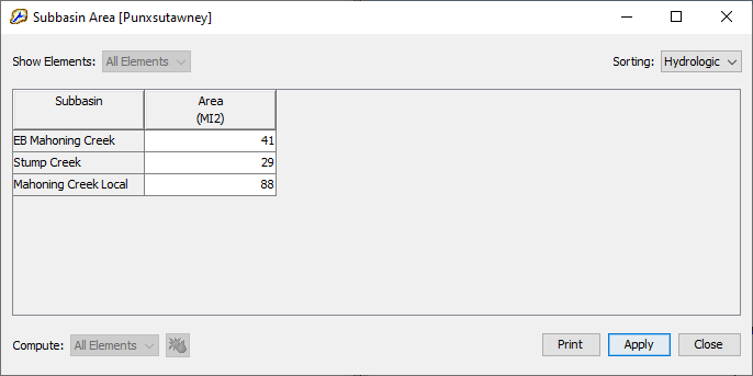
- Set up Baseflow Parameters. From the Parameters menu, select the Baseflow and then Linear Reservoir option.
Enter the values from the table below, then click the Close button when finished. Be sure to select the correct type of initial condition: Discharge Per Area. Also, be sure to select the correct number of layers:
Subbasin Number of Layers Initial Type GW 1 Initial GW 1 Fraction GW 1 Coefficient GW 1 Reservoirs GW 2 Initial GW 2 Fraction GW 2 Coefficient GW 2 Reservoirs EB Mahoning Creek 2 Discharge Per Area 1 0.5 70 1 1 0.5 100 1 Stump Creek
2 Discharge Per Area 1
0.5 70 1 1 0.5 100 1 Mahoning Creek Local 2 Discharge Per Area 1 0.5 70 1 1 0.5 100 1 Parameters | Baseflow | Linear Reservoir
1
Input baseflow Parameters provided in the table above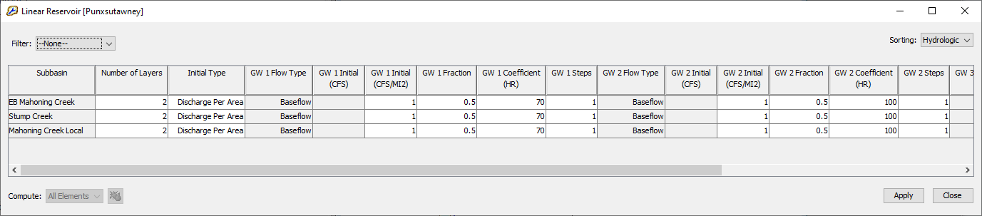
Set up Loss Parameters. From the Parameters menu, select the Loss and then Initial and Constant option. Enter the values from the table below, then click the Close button when finished.
Subbasin Initial Loss (in) Constant Rate (in/hr) Impervious (%) EB Mahoning Creek 1 0.1 0 Stump Creek 1 0.1 0 Mahoning Creek Local 1 0.1 0 Parameters | Loss | Initial and Constant

Input the Initial loss, Constant rate and Impervious parameters provided in the table above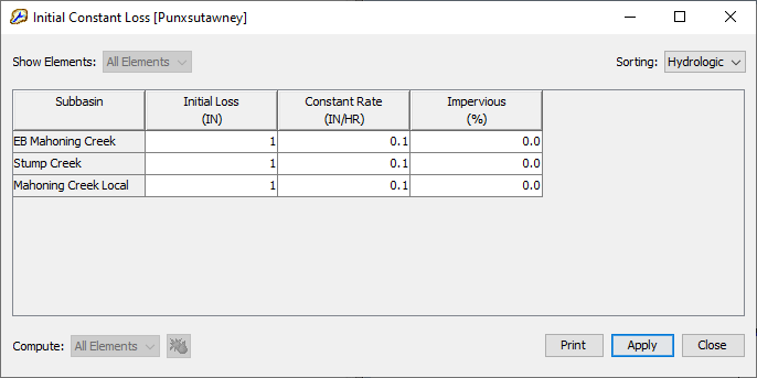
From the Parameters menu, select the Transform and then Clark Unit Hydrograph option. Enter the values from the table below, then click the Close button when finished.
Subbasin Time of Concentration (hr) Storage Coefficient (hr) EB Mahoning Creek 7 11 Stump Creek 9 12 Mahoning Creek Local 10 13 Parameters | Transform | Clark Unit Hydrograph

Input Time of Concentration and Storage Coefficients provided in the table above
Question: In steps 20-23 modeling methods are parameterized from the Parameters menu. What is an alternative way to parameterize modeling methods in the HEC-HMS user interface?The component editor is an alternative way to parameterize the model one element at a time. Globally editing tends to be much faster when parameterizing multiple elements of the same modeling method.

- On the basin map in the desktop area, click the Reach-1 element to open its Component Editor. Click on the Routing tab and then enter a lag value of 300 minutes.
Summary
You have now completed steps for adding hydrologic elements to a basin model, connected the hydrologic elements to form a hydrologic network, and parameterized the methods used to simulate hydrologic processes.

Continue to Creating a New Meteorologic Model