Download PDF
Download page Spillways.
Spillways
Spillways typically represent structures at the top of the dam that allow water to go over the dam top in an uncontrolled manner. Up to ten independent spillways can be included in the reservoir. There are three different methods for computing outflow through a spillway: Broad-Crested, Ogee, and User Specified. The broad-crested and ogee methods may optionally include gates. If no gates are selected, then flow over the spillway is unrestricted. When gates are included, the flow over the spillway will be controlled by the gates. Up to ten independent gates may be included on a spillway. The spillway may release to the main channel or an auxiliary location.
The calculations for spillways begin with the standard weir equation:
| Q=CLH^{\frac{3}{2}} |
where:
Q = Discharge over the weir or spillway crest.
C = Discharge coefficient, accounts for energy losses as water enters the spillway, flows through the spillway, and eventually exits the spillway. Typical values will range from 2.6 to 4.0 depending upon the shape of the spillway crest.
L = Length of the spillway crest.
H = Upstream energy head above the spillway crest.
HEC-HMS includes a secondary calculation to determine whether tailwater conditions alter the computed discharge, and the program adjusts accordingly. Details on the application of this equation can be found in the HEC-RAS Technical Reference Manual. HEC-HMS uses the same approach, with some simplifications.
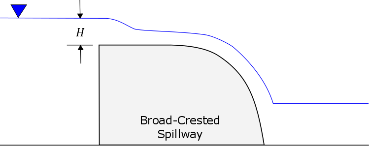
Broad-Crested Spillway
The broad-crested spillway allows for uncontrolled flow over the top of the reservoir according to the weir flow assumptions.
The discharge coefficient C accounts for energy losses as water enters the spillway, flows through the spillway, and eventually exits the spillway. Depending on the exact shape of the spillway, typical values range from 1.10 to 1.66 in System International units (2.0 to 3.0 US Customary units) (Note: RAS manual says 2.6-3.1).
For each time step within the simulation, the head is estimated using the user-specified crest elevation of the spillway and the reservoir pool elevation.
|
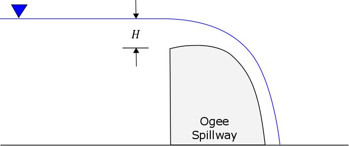
Ogee Spillway
The ogee spillway allows for uncontrolled flow over the top of the reservoir according to the weir flow assumptions. However, the discharge coefficient in the weir flow equation is automatically adjusted when the upstream energy head is above or below the design head.
The ogee spillway may be specified with concrete or earthen abutments. These abutments should be the dominant material at the sides of the spillway above the crest. The selected material is used to adjust energy loss as water passes through the spillway. The spillway can be conceptually represented using one, two, or no abutments.
The ogee spillway is assumed to have an approach channel that moves water from the main reservoir to the spillway. If there is such an approach channel, you must specify the depth of the channel, and the energy loss that occurs between the main reservoir and the spillway. If there is no approach channel, the depth should be the difference between the spillway crest and the bottom of the reservoir, and the loss should be zero.
The crest elevation and length of the spillway are needed, as are the apron elevation and width.
The design head is the total energy head for which the spillway is designed. The discharge coefficient will be automatically calculated when the head on the spillway departs from the design head.
|
Don't know what equations are used here. Linear interpolation
Calculate the head ratio. If less than design ratio, then X, if greater than or equal to design ratio, then …
Check RAS. It's complicated.
Gate flow equation – either radial or sluice.
- gate coefficient
- gate width
- trunnion^trunnion exponent
- gate opening^opening exponent
- head^head exponent
Specified Spillway
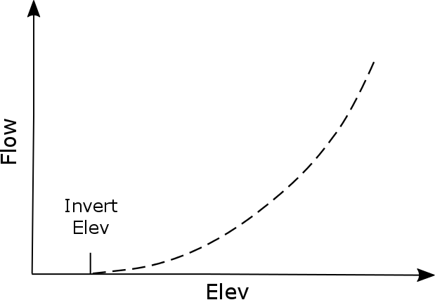
The user-specified spillway can be used to represent spillways with flow characteristics that cannot be represented by the broad-crested or ogee weir assumptions. The user must create an elevation-discharge curve (Figure X) that represents the spillway discharge as a function of reservoir pool elevation, and HEC-HMS determines discharge though a basic table lookup approach. At this time there is no ability to include submergence effects on the specified spillway discharge. Therefore the user-specified spillway method should only be used for reservoirs where the downstream tailwater stage cannot affect the discharge over the spillway.
|
Gated Spillways
Spillway gates are an optional part of specifying the configuration of a spillway. They may be included on either broad-crested or ogee spillways.
An important part of defining gates on a spillway is the specification of how each gate will operate. It is rare that a gate is simply opened a certain amount and then never changed. Usually gates are changed on a regular basis in order to maintain the storage in the reservoir pool at targets; usually seasonal targets will be defined in the reservoir regulation manual. Under some circumstances, the gate operation may be changed to prevent flooding or accommodate other special concerns. At this time there is only one method for controlling spillway gates but additional methods will be added in the future.
The Fixed opening control method only accommodates a single setting for the gate. The distance between the spillway and the bottom of the gate is specified. The same setting is used for the entire simulation time window.
Sluice Gate
A sluice gate moves up and down in a vertical plane above the spillway in order to control flow. The water passes under the gate as it moves over the spillway. For this reason it is also called a vertical gate or underflow gate.
The width of the sluice gate must be specified. It should be specified as the total width of an individual gate.
The gate coefficient describes the energy losses as water passes under the gate. Typical values are between 0.5 and 0.7 depending on the exact geometry and configuration of the gate.
The orifice coefficient describes the energy losses as water passes under the gate and the tailwater of the gate is sufficiently submerged. A typical value for the coefficient is 0.8.
The HEC-RAS Hydraulic Reference Manual describes sluice gate flow calculations as follows:
An example sluice gate with a broad crest is shown in the figure below.
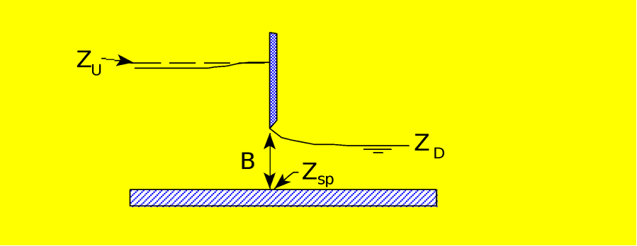
Figure X Example Sluice Gate with Broad Crested Spillway. (source: HEC-RAS Hydraulic Reference Manual)
The equation for a free flowing sluice gate is as follows:
| Q = CWB \sqrt{2gH} |
where: H = Upstream energy head above the spillway crest (ZU - Zsp)
C= Coefficient of discharge, typically 0.5 to 0.7
When the downstream tailwater increases to the point at which the gate is no longer flowing freely (downstream submergence is causing a greater upstream headwater for a given flow), the program switches to the following form of the equation:
| Q=CWB \sqrt{2g3H} |
Where: H= ZU - ZD
Submergence begins to occur when the tailwater depth above the spillway divided by the headwater energy above the spillway is greater than 0.67. Equation 8-5 is used to transition between free flow and fully submerged flow. This transition is set up so the program will gradually change to the fully submerged Orifice equation (Equation x) when the gates reach a submergence of 0.80.
Radial Gate
A radial gate rotates above the spillway with water passing under the gate as it moves over the spillway. This type of gate is also known as a tainter gate.
The width of the radial gate must be specified. It should be specified as the total width of an individual gate.
The gate coefficient describes the energy losses as water passes under the gate. Typical values are between 0.5 and 0.7 depending on the exact geometry and configuration of the gate.
The orifice coefficient describes the energy losses as water passes under the gate and the tailwater of the gate is sufficiently submerged. A typical value for the coefficient is 0.8. The pivot point for the radial gate is known as the trunnion. The height of the trunnion above the spillway must be entered. The trunnion exponent is part of the specification of the geometry of the radial gate. A typical value is 0.16. The gate opening exponent is used in the calculation of flow under the gate. A typical value is 0.72. The head exponent is used in computing the total head on the radial gate. A typical value is 0.62.
The HEC-RAS Hydraulic Reference Manual describes radial gate calculations as follows:
An example radial gate with an ogee spillway crest is shown in Figure X. (copied out of RAS)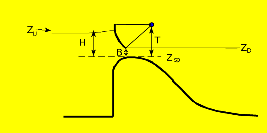
Figure X Example Radial Gate with an Ogee Spillway Crest
The flow through the gate is considered to be "Free Flow" when the downstream tailwater elevation (ZD) is not high enough to cause an increase in the upstream headwater elevation for a given flow rate. The equation used for a Radial gate under free flow conditions is as follows:
| Q=C \sqrt{2g}W T^{TE} B^{BE} H^{HE} |
where:
Q= Flow rate in cfs
C= Discharge coefficient (typically ranges from 0.6 - 0.8)
W= Width of the gated spillway in feet
T= Trunnion height (from spillway crest to trunnion pivot point)
TE= Trunnion height exponent, typically about 0.16 (default 0.0)
B= Height of gate opening in feet
BE= Gate opening exponent, typically about 0.72 (default 1.0)
H= Upstream energy head above the spillway crest ZU - Zsp
HE= Head exponent, typically about 0.62 (default 0.5)
ZU= Elevation of the upstream energy grade line
ZD= Elevation of the downstream water surface
Zsp= Elevation of the spillway crest through the gate
When the downstream tailwater increases to the point at which the gate is no longer flowing freely (downstream submergence is causing a greater upstream headwater for a given flow), the program switches to the following form of the equation:
| Q=C \sqrt{2g}W T^{TE} B^{BE} (3H)^{HE} |
where: H=ZU - ZD
Submergence begins to occur when the tailwater depth divided by the headwater energy depth above the spillway, is greater than 0.67. Equation 8-2 is used to transition between free flow and fully submerged flow. This transition is set up so the program will gradually change to the fully submerged Orifice equation when the gates reach a submergence of 0.80. The fully submerged Orifice equation is shown below:
| Q=CA \sqrt{2gH} |
where:
A= Area of the gate opening.
H= ZU - ZD
C= Discharge coefficient (typically 0.8)
Sluice gate always uses 0.5 head exponent. It appears the same for radial gate.
They are currently rebuilding to allow the user to specify the opening.
New outlet that allows for gates (no orifice or culvert gate)