Download PDF
Download page Outlets.
Outlets
Outlets typically represent structures near the bottom of the dam that allow water to exit in a controlled manner. They are often called gravity outlets because they can only move water when the head in the reservoir is greater than the head in the tailwater. Up to ten independent outlets can be included in the reservoir.
Culvert Outlet
The culvert outlet can handle many flow types including pressure flow, so it allows for partially full or submerged flow through a culvert with a variety of cross-sectional shapes. Culvert flow calculations can be complicated, but the approach taken by HEC-HMS is shared with RAS – it simplifies the analysis by considering the flow either Inlet Control or Outlet Control. As described in Chapter 6 of the HEC-RAS Technical Reference Manual, "Inlet control flow occurs when the flow capacity of the culvert entrance is less than the flow capacity of the culvert barrel. The control section of a culvert operating under inlet control is located just inside the entrance of the culvert. The water surface passes through critical depth at or near this location, and the flow regime immediately downstream is supercritical. For inlet control, the required upstream energy is computed by assuming that the culvert inlet acts as a sluice gate or as a weir. Therefore, the inlet control capacity depends primarily on the geometry of the culvert entrance. Outlet control flow occurs when the culvert flow capacity is limited by downstream conditions (high tailwater) or by the flow carrying capacity of the culvert barrel. The HEC RAS culvert routines compute the upstream energy required to produce a given flow rate through the culvert for inlet control conditions and for outlet control conditions. In general, the higher upstream energy "controls" and determines the type of flow in the culvert for a given flow rate and tailwater condition. For outlet control, the required upstream energy is computed by performing an energy balance from the downstream section to the upstream section. The HEC RAS culvert routines consider entrance losses, friction losses in the culvert barrel, and exit losses at the outlet in computing the outlet control headwater of the culvert."
HEC-HMS shares the RAS culvert routines, and thus requires the same input data. RAS, however, assumes a roadway crest, whereas HEC-HMS does not. Figure 1 depicts the relationships between upstream energy and flow rate for outlet control and inlet control flows.
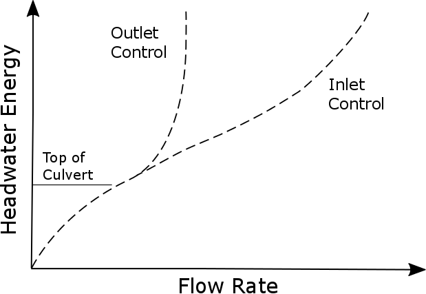
Thus, there are three different solution methods for culvert outlets, allowing for Inlet Control, Outlet Control, or Automatic. Automatic allows the program to determine whether the flow is inlet or outlet controlled at each timestep. This approach is highly recommended, unless the user is modeling a special case.
Table 2. Culvert Outlet Settings
Settings | Options |
|---|---|
Direction | Main or Auxiliary |
Number of Barrels | Select up to 10 identical barrels |
Solution Method | Automatic, Inlet Control, Outlet Control |
Shape | Arch, Box, Circular, Con Span, Elliptical, High-Profile Arch, Low-Profile Arch, Pipe Arch, Semi-Circular |
Depending on which shape you select, you have a subset of Charts and Scales to choose from. | |
Settings | Depending on which shape you select, you have a subset of settings to choose from. |
The limitations to the culvert calculations are that no upstream or downstream cross sections are used. So the energy gradeline is calculated assuming a quiescent, level pool above the inlet and a quiescent stilling basin at the outlet.
Inlet Controlled
Use this method when the culvert outflow is controlled by a high pool elevation in the reservoir. See equations 6-2 and 6-3 in the HEC-RAS Technical Reference Manual for the calculations used. HEC-HMS departs from the RAS approach at the Outlet Controlled Headwater. Equation 6-4 is modified for HEC-HMS so that the velocities are assumed zero. The same is true for equation 6-7.
Outlet Controlled
Outlet controlled calculation can handle zero, partial, pressurized flow. It changes based on the shape of the culvert. Culvert outflow that is controlled by a high tailwater condition uses this
Automatic
In order to determine which type of flow rules, energy minimization is performed. Flow is computed using inlet or outlet control and the lower flow is chosen.
Outlet Shape
You must specify the outlet shape and related parameters so that the HEC-HMS can use the appropriate equations. Table 3 shows a list of the outlet cross section shapes and the associated parameters used in the calculations.
Table 3. Listing of which parameters are required for each cross section shape.
Cross Section Shape | Diameter | Rise | Span |
|---|---|---|---|
Circular | X | ||
Semi Circular | X | ||
Elliptical | X | X | |
Arch | X | X | |
High-Profile Arch | X | ||
Low-Profile Arch | X | ||
Pipe Arch | X | X | |
Box | X | X | |
Con Span | X | X |
Orifice Outlet
The orifice outlet assumes a large outlet with sufficient submergence for orifice flow conditions to dominate. It should not be used to represent an outlet that may flow only partially full. The necessary submergence is typically present for low level reservoir outlets, but it may not be assured for small reservoirs, such as those on farms. If there is any uncertainty about whether or not the large orifice approach is appropriate, it is best to use the Culvert approach instead. The downside is that it may take ten to twenty times longer to calculate.
In order to ensure that the outlet is experiencing pressure flow conditions, the inlet of the structure should be submerged at all times by a depth at least 0.2 times the height of the orifice outlet. The approximate height is estimated to be the square root of the area. The water elevation is calculated and compared accordingly. HEC-HMS will check this condition and return and error messages with the number of times the condition was not met.
Table 4. Orifice Outlet Settings
Settings | Options |
|---|---|
Direction | Main or auxiliary |
Number of Barrels | You must select up to 10 identical barrels |
Center Elevation | center of the cross-sectional flow area |
Area | cross-sectional flow area |
Coefficient | dimensionless discharge coefficient |
The center elevation specifies the center of the cross-sectional flow area. It is used to compute the head on the outlet, so no flow will be released until the reservoir pool elevation is above this specified elevation. The cross-sectional flow area of the outlet must be specified. The orifice assumptions are independent of the shape of the flow area. The dimensionless discharge coefficient must be entered. This parameter describes the energy loss as water exits the reservoir through the outlet.
Section 6 of the HEC-RAS Technical Reference Manual includes detailed descriptions and equations used in culvert hydraulics and flow analysis. Since much of the approach is shared with HEC-HMS, these descriptions are not repeated here. Refer to the HEC-RAS manual for details on the algorithms. Note that the difference between the HEC-RAS and the HEC-HMS outlet flow calculations is that HEC-HMS does not consider flow in upstream or downstream cross sections, thus the equations are simplified by assuming zero velocity.
Outlet Tower
The Outlet Tower option provides a detailed representation of intake tower outflow control, improving both hydraulic simulations and sediment routing. By modeling the timing and magnitude of releases through configurable intake openings, this approach more accurately simulates reservoir water surface elevations and spillway activation. Additionally, the vertical configuration of the tower openings influences how sediment sizes are partitioned, distinguishing between material trapped within the basin and sediment routed downstream. This method is particularly suited for reservoirs with multi-level intake structures where sediment deposition and regulated releases interact dynamically.
To ensure accurate modeling, all elevation parameters must be referenced to a consistent vertical datum, matching the reservoir and outlet elevation data. The outlet tower calculation dynamically switches between weir and orifice flow conditions based on water surface elevations relative to the opening sills. Sediment routing is coupled with hydraulic calculations: openings submerged in sediment will have their effective flow area reduced, and seepage through deposited material is computed using the specified hydraulic conductivity. If hydraulic conductivity is set to zero, seepage is disabled.

As shown in Table 5 and Figure 2, all input parameters are described below.
The Number of Levels defines the vertical staging of the intake structure. This value is typically derived from as-built construction drawings or verified during field inspections. The Cross-Section Area represents the internal volume of the tower shaft, which can be calculated from engineering plans or estimated using high-resolution aerial imagery. The Base Elevation establishes the foundation datum for the tower and should align with terrain data or survey records.
Below the tower structure, the Base Orifice Area and Base Orifice Coefficient characterize the downstream conveyance pipe or outlet works. These parameters govern energy losses as water exits the tower base and are generally sourced from hydraulic design manuals or facility specifications.
Sediment routing is integrated directly into the hydraulic model. The Hydraulic Conductivity parameter quantifies the permeability of accumulated sediment and debris within the basin. Seepage calculations are only activated when openings become submerged in deposited material. Setting this value to 0 ft/day disables seepage computation. Recommended values should be derived from laboratory soil samples or regional hydrogeological data for the contributing watershed.
Within the Level configuration tab, each intake tier is defined independently. The Number of Openings, Opening Height, and Opening Width establish the geometric pass-through capacity for each level. These dimensions are standard features documented in facility as-builts. The Sill Elevation marks the invert of the openings for a specific level and must be reported in the same vertical datum as the reservoir stage data.
Flow regime transitions are handled automatically based on reservoir depth. The Orifice Coefficient governs flow calculations when openings are fully submerged, representing energy dissipation at the intake. This coefficient is dynamically adjusted to account for the unblocked flow area when sediment partially obstructs the opening. Conversely, the Weir Coefficient applies only during free-surface conditions, governing flow over the opening crest when water levels do not fully submerge the intake. Both coefficients should be selected based on standard hydraulic references for the specific gate or opening geometry.
Table 5. Outlet Tower Settings
| Parameter | Description |
|---|---|
| Number of Levels | Defines the total number of opening levels in the outlet tower |
| Cross-Section Area | Defines the internal cross-sectional area of the outlet tower structure |
| Base Elevation | Specifies the elevation at the bottom of the outlet tower |
| Base Orifice Area | Defines the cross-sectional area of the outlet pipe or structure beneath the tower |
| Base Orifice Coefficient | Dimensionless discharge coefficient for flow through the base orifice, representing energy losses |
| Hydraulic Conductivity | Defines the permeability of deposited sediment, used to compute seepage through submerged openings |
| Number of Openings | Specifies the quantity of openings at a given level |
| Opening Height | Defines the vertical height of each opening within the level |
| Opening Width | Defines the horizontal width of each opening within the level |
| Sill Elevation | Specifies the elevation at the bottom of the openings for the level |
| Orifice Coefficient | Dimensionless discharge coefficient for submerged (orifice) flow conditions |
| Weir Coefficient | Discharge coefficient for free-surface (weir) flow conditions over the opening crest |
