Download PDF
Download page GIS Menu.
GIS Menu
Twelve tools are available under the GIS menu (Figure 1). Many of these tools are not activated until other requirements are met; often this requirement is to have used other tools in this menu. For watershed delineation functions, the menu serves as a roadmap: the workflow proceeds from top to bottom in order.
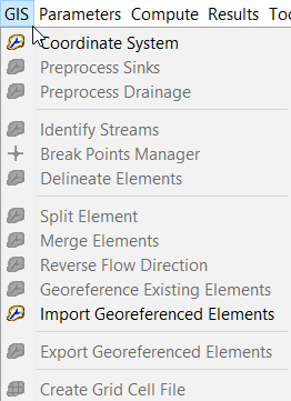
Coordinate System
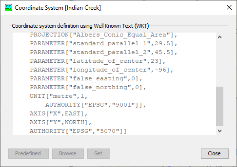
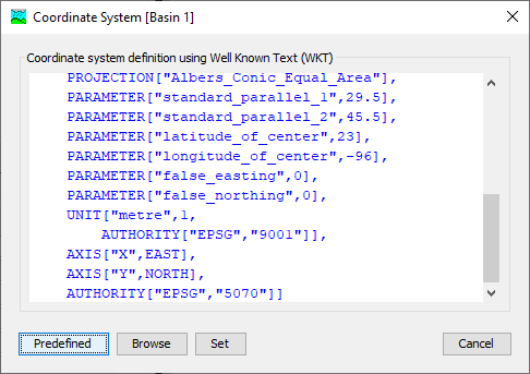
This tool allows you to set or view the coordinate system for a basin model. If a basin model is selected and it has a coordinate system assigned, selecting GIS > Coordinate System will show the current coordinate system (Figure 2).
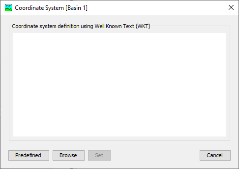
If a basin model is selected and no coordinate system has been assigned yet, selecting GIS > Coordinate System will prompt you to choose a coordinate system for the spatial referencing of the basin model (Figure 3). First, you will see a blank coordinate system selection prompt (Figure 3). Here you can choose to use a predefined coordinate system if you select the Predefined button. You may also choose to browse to GIS data that have a coordinate system reference and select it, extracting its coordinate system definition by pressing Browse. Finally, you may copy and paste an OGC WKT definition for a coordinate system in the text field. You may cancel the procedure by pressing Cancel. Once the text has been populated in the text field using either the predefined, existing GIS data or copied OGC WKT, you can set the basin coordinate system using the Set button.
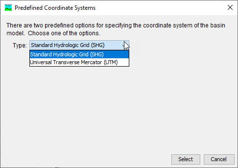
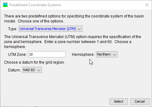
HEC-HMS provides two predefined coordinate systems: Standard Hydrologic Grid (SHG) and Universal Transverse Mercator (UTM). Choosing the Predefined setting produces a selection dialog with two options (Figure 4). Using SHG requires no additional information. Using UTM requires the UTM zone, hemisphere and datum to be specified (Figure 5). After setting the necessary options, pressing the Select button will populate the coordinate system selection dialog text field with the appropriate information. Pressing Cancel or the X will cancel the process.
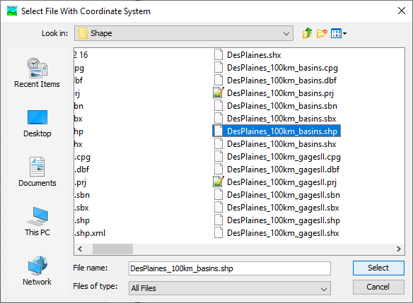
Using the Browse option allows you to navigate to any GIS data with a coordinate system specification (e.g. shape file, raster data, .prj file, etc.) and select it so that HEC-HMS can extract its coordinate system specification (Figure 6).
Alternatively, you may enter the coordinate system specification in the text field using an OGC WKT format. All three of these options will result in text in the text field (Figure 7). Once the coordinate system is specified in that text field, pressing Set will set the coordinate system for that basin model.
Preprocess Sinks
This tool will be available only if the following conditions are met:
- You have selected a basin model
- The basin model has a terrain data component assigned to it
Selecting GIS > Preprocess Sinks will run a pit removal algorithm on the terrain data assigned to the selected basin model and produce a new, hydrologically-corrected DEM and a raster indicating the location of sinks and the depth they were filled. Those two new rasters are added to the Map Layers list as "Sink Fill" and "Sink Locations", respectively.
If the terrain data assigned to the basin model is a hydrologically-corrected DEM, then this step is not necessary.
When the tool is run on large terrain datasets, it may produce an indefinite progress bar such as the one in Figure 8. The indefinite progress bars purpose is to indicate progress, without estimating the time to completion.

Preprocess Drainage
This tool will be available only if the following conditions are met:
- You have selected a basin model
- The basin model has a terrain data component assigned to it
Selecting GIS > Preprocess Drainage will run an algorithm to determine the flow direction and flow accumulation for each grid cell in the terrain data raster. If you run the Preprocess Sinks command first, this algorithm will use the hydrologically-corrected DEM. If not, it will use the default elevation dataset provided by the terrain data component. Both of the resulting rasters are added to the Map Layers list as "Flow Direction" and "Flow Accumulation", respectively.
When the tool is run on large terrain datasets, it may produce an indefinite progress bar such as the one in Figure 9.

Identify Streams
This tool will be available only if the following conditions are met:
- You have selected a basin model
- The basin model has a terrain data component assigned to it
- The Preprocess Drainage tool has been run
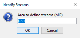
Selecting GIS > Identify Streams for the first time on a basin model will produce a prompt that requires you to enter the drainage accumulation threshold that will define where a stream starts, as in Figure 10. A default is provided based on the resolution of the raster, but may produce too fine (or too coarse) of a threshold for your intended delineation. The value you enter will be the approximate drainage area for the subbasin elements that result.
When the tool is run on large terrain datasets, it may produce an indefinite progress bar such as the one in Figure 11.

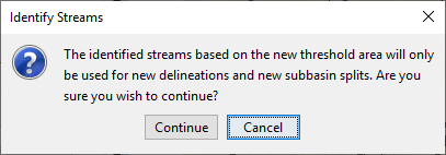
If you have previously run the Identify Streams tool and you run it again, you will see the prompt in Figure 12.
Break Points Manager
This tool will be available only if the following conditions are met:
- You have selected a basin model
- The basin model has a terrain data component assigned to it
- The Identify Streams tool has been run
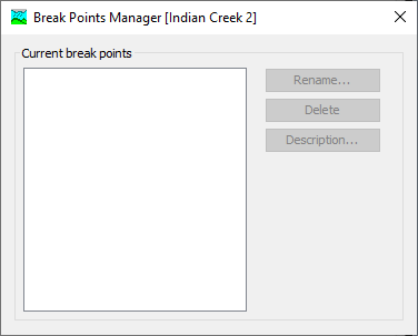
The Break Points Manager (Figure 13) will allow you to view, rename, delete or modify the description of any break points defined in the basin model. By default, a basin model does not contain any break points. At least one break point, defining a watershed outlet, is necessary in order to perform a watershed delineation. Additional break points will force delineation of a subbasin element at that location. Break points are created using the Break Point Creation Tool in the Components Toolbar (Figure 14).

Selecting the Break Point Creation Tool and clicking in the basin model map window will produce a prompt (Figure 15) that asks for the name of the break point, as well as an optional description. If the text box is left blank, or the name is invalid, the Create button will not be available. Break points are shown on the basin map as red circles.

Delineate Elements
This tool will be available only if the following conditions are met:
- You have selected a basin model
- The basin model has a terrain data component assigned to it
- The Identify Streams tool has been run
- At least one break point has been defined
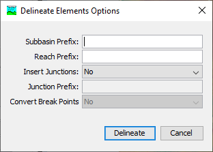
Selecting GIS > Delineate Elements for the first time on a basin model will produce a prompt that requires you to enter some naming scheme and delineation options (Figure 16). The Subbasin Prefix, Reach Prefix and Junction Prefix options are text strings that prepend the automatic numbering scheme for the elements created in delineation. For example, if you enter "S_" as the Subbasin Prefix, the subbasins created in the delineation process will be named "S_1", "S_2", and so on. The Insert Junctions option will automatically insert junctions above reaches when reaches are created in the delineation procedure. The Convert Break Points option will make any locations where there are break points, computation points in the basin model. The most downstream break point, which serves as a watershed outlet, will cause creation of a sink element at that location.
When the tool is run on large terrain datasets, it may produce an indefinite progress bar such as the one in Figure 17.

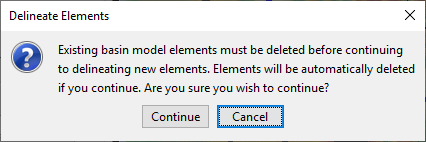
The Delineate Elements tool can be re-run on a basin model, for example if you change the threshold for the Identify Streams tool and wish to re-delineate, or have made other changes to the basin model and wish to revert. When it is re-run, the Delineate Elements Options prompt (Figure 16) will appear, giving you an opportunity to change delineation options. If you run the tool with an existing delineation, you will see a dialog that indicates that a new delineation will delete an old one (Figure 18). Selecting Continue will delete existing elements and re-delineate.
Split Elements
This tool will be available only if the following conditions are met:
- You have selected a basin model
- The basin model has a terrain data component assigned to it
- The Delineate Elements tool has been run
- Exactly one subbasin or reach element has been selected
Selecting GIS > Split Elements will allow you to choose where to divide a subbasin or reach element into two smaller elements.
Merge Elements
This tool will be available only if the following conditions are met:
- You have selected a basin model
- The basin model has a terrain data component assigned to it
- The Delineate Elements tool has been run
- Exactly two subbasin or two reach elements have been selected
Selecting GIS > Merge Elements will allow you to choose to combine two subbasin or two reach element into one larger element. HEC-HMS will not check to make sure that combining the elements makes any hydrologic sense, only that the two elements either are immediately upstream and downstream of each other, or are adjacent and share a common outlet point. It is up to the user to ensure that merging the selected elements makes sense. The result of running the tool is a single element where there were previously two, with a new element name.
Reverse Flow Direction
Using the GIS > Reverse Flow Direction tool will swap the upstream and downstream endpoints of a reach element, effectively reversing the direction that the reach flows. It will affect the downstream element for the reach, as well as any elements that flow downstream into the reach. It is typically used in cases where imported elements flow in the incorrect direction.
Georeference Existing Elements
The georeference existing elements option is used to add GIS features to existing subbasin, reservoir, and reach elements. ESRI Shape Files are the GIS file format required for importing GIS features. The shape files must contain a name attribute that the user selects when importing the GIS features into a basin model. A coordinate system must be defined for the basin model prior to georeferencing elements.
The Georeference Existing Elements wizard is similar to the Import Georeferenced Elements wizard, there are three steps for the user to select the element type, GIS file (shape file), and the name attribute within the shape file. The Georeference Existing Elements option will result in GIS features for only those elements already in the basin model model that have a name matching the name in the GIS layer's attribute table. The Georeference Existing Elements option is useful for HEC-HMS projects created with earlier versions of the software that only have element icons for subbasins, reaches, and reservoirs. It is an options for adding more of a GIS look and feel to the basin model map.
Geometric data in the ESRI Shape Files is matched to the elements using the element name. The element name is specified when creating the element in the Basin Model Map window. The geometric data must have the same element name when georeferencing existing elements. As mentioned above, the element name of the geometric data is specified using the "Name" field property in the DBF file (the user can choose the attribute field containing the feature names when importing GIS features). The example project "river bend" includes GIS features for the subbasin elements. The example project can be installed from the Help menu; select the Install Sample Projects menu command.
Import Georeferenced Elements
The import georeferenced elements option is used to add new elements to the basin model, while also adding GIS features for the new elements. ESRI Shape Files are the GIS file format required for importing GIS features. The shape files must contain a name attribute that the user selects when importing the GIS features into a basin model. A coordinate system must be defined for the basin model prior to importing georeferenced elements.
After the coordinate system has been defined, GIS features can be imported for existing elements, or new elements can be added using GIS features. Figure 19 shows step 1 of 3 for the Import Georeferenced Elements wizard. This wizard will import new HEC-HMS elements into the basin model. As stated in the import wizard, polygon and line information are imported when the subbasin, reach, or reservoir elements are added to the basin model map. Step 1 requires the user to select the "Element Type" to import. The available options are Subbasin, Reach, and Reservoir. Once the element type is selected, click the Next button.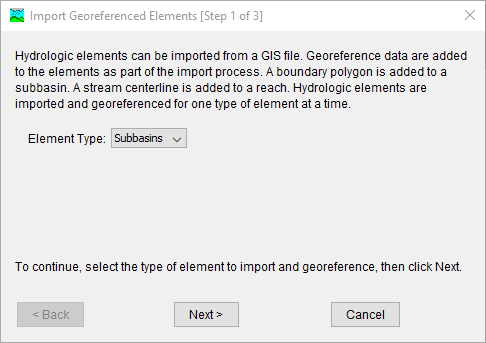
Figure 20 shows the second step of the Import Georeferenced Elements wizard. The user must choose a shape file. Click the browse button and navigate to a directory with the shape file and choose the appropriate file, choose the file with an extension of .shp. Click the Next > button to go to step three.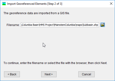
Figure 21 shows the third step of the Import Georeferenced Elements wizard. The user must choose a field within the shape file's attribute table. Select the appropriate name field and click the Finish button. The program will import the elements in the shape file while also adding GIS features for those new element.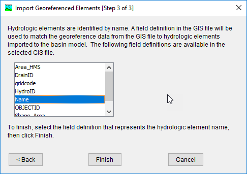
Export Georeferenced Elements
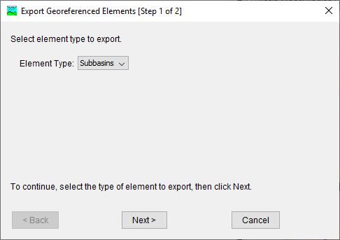
After delineating, you may wish to export the resulting subbasin boundary and reach lines for use outside of HEC-HMS. These features can be exported using the GIS > Export Georeferenced Elements tool. When selecting the tool, you first will be prompted to select whether to export subbasins or reaches (Figure 22.) Pressing Cancel will exit the export wizard. Pressing Next > will take you to the second step of the process, exporting the selected element type.
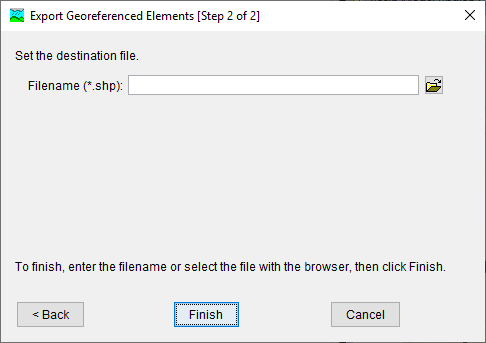
Exported features will be in ESRI shapefile format, and you need to specify the destination file path and name using the text field or browser on the second step of the wizard (Figure 23.) If you select < Back you can re-choose which element type you would like to export. Cancel will exit the wizard. Finish will create the exported shapefile in the specified location.
Create Grid Cell File
A grid cell file is required in order to apply gridded precipitation to a basin model, or when using any of the gridded methods in the meteorologic model. A grid cell file is also required to use the ModClark transform method and any of the gridded loss methods. There is a option to create a grid cell file from the GIS menu. The grid cell file should only be created after delineating subbasin and reach elements, and updating element names with names that are appropriate for the study. The grid cell file must be re-created if any of the subbasin names are modified.
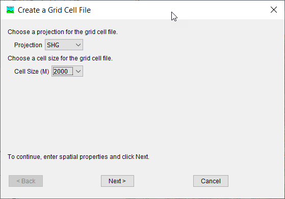
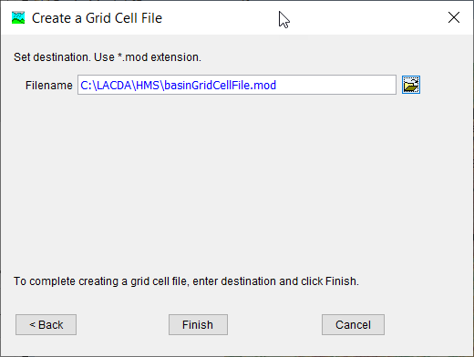
Figure 24 shows the first editor in the Create a Grid Cell File wizard that is opened by clicking GIS > Create Grid Cell File. The user must select the grid projection first, the options include Standard Hydrologic Grid (SHG) or one of the UTM projections. The user must also select the grid resolution from a drop down list. The grid resolution must match the resolution of all gridded meteorologic data-sets and any parameter grids. Figure 25 shows the second editor in the Create a Grid Cell File wizard. The user must select a file location and name for the grid cell file. By default, the file extension is *.mod. When clicking the Finish button, the program will create the user specified grid, intersect the grid with the subbasin boundaries, and create a text file containing the grid cells within each subbasin, their area, and their travel length. The travel length is computed using the flow direction grid. The program computes an area weighted travel length for each of the SHG or UTM grid cells.
After the grid cell file is created, it must be loaded into the project using the Create a Grid Region wizard.
