Download PDF
Download page Diversion.
Diversion
A diversion is an element with two outflows, main and diverted, and one or more inflows. Inflow comes from other elements in the basin model. If there is more than one inflow, all inflow is added together before computing the outflows. Six methods are available for computing the diverted flow that will be taken out of the channel. All flow that is not diverted becomes the main outflow. Diverted flow can be connected to an element that is computationally downstream. The diversion can be used to represent weirs or pump stations that divert flow into canals or off-stream storage. The diversion element includes optional properties for limiting the amount of diverted flow. Unregulated outputs can also be computed for elements located downstream of diversions. Access the Component Editor by clicking the diversion element icon on the "Components" tab of the Watershed Explorer (Figure 1).
Connecting Diversion Flow
You may optionally choose to connect the diversion flow to another point in the element network. In this case, the diversion flow can become inflow to a junction or other element. This can be useful for representing water that is diverted at a point location in a watershed, moves through a separate channel network, and rejoins the stream from which it was diverted. Properly configured, it can also be used to represent inter-basin transfers. If you do not connect the diversion flow, then it is removed from the system at the diversion element. In either case, the time-series of diversion flow is shown in the graph and time-series tables for the diversion element. The amount of diversion flow is also shown in the diversion element summary table.
The connection for diversion flow is specified on the Component Editor for the diversion element. Access the Component Editor by clicking the diversion element icon on the "Components" tab of the Watershed Explorer (Figure 1). You can also access the Component Editor by clicking on the element icon in the basin map, if the map is currently open. The selection list includes all elements that are computationally downstream of the diversion element. Select an element from the list to connect the diversion flow to that element as an inflow, or choose Not Connected.
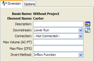
Figure 1. Diversion component editor. Connecting the diverted flow is optional, as is the maximum volume and maximum diversion flow.
Limiting Flow or Volume
Two options are available for limiting the amount of water removed from the channel as diversion flow. If neither option is used, the diversion flow will not be limited. If one or both options are used, diversion flow will be computed first without any limitations then reduced as necessary to meet the optional requirements. The optional limitations are included on the Component Editor for the diversion element. Access the Component Editor by clicking the diversion element icon on the "Components" tab of the Watershed Explorer (Figure 1). You can also access the Component Editor by clicking on the element icon in the basin map, if the map is currently open.
The first option for limiting diversion flow is the specification of a maximum volume. Diversion flow is computed normally and the cumulative volume of diverted flow is tracked. Once the cumulative volume reaches the specified maximum volume, all future diversion flow will be set to zero.
The second option for limiting diversion flow is the specification of a maximum allowed flowrate. Diversion flow is initially computed without limitation. For every time interval, the computed diversion flow is compared to the specified maximum flow. If the computed flow is above the maximum flow, the diversion flow is reduced to the specified maximum flow.
Selecting a Divert Method
While a diversion element conceptually represents a diversion from the stream or river, the actual calculations are performed by a divert method contained within the diversion element. Six methods are currently available for computing the diversion flow. The divert method is selected on the Component Editor for the diversion element. Access the Component Editor by clicking the diversion element icon on the "Components" tab of the Watershed Explorer (Figure 1). You can also access the Component Editor by clicking on the element icon in the basin map, if the map is currently open. You can select a divert method from the list of six available choices. If you choose the None method, the diversion will pass all flow down the main connection and no flow will be diverted. Use the selection list to choose the method you wish to use. Each diversion element may use a different method or several diversions may use the same method.
The parameters for the divert method are presented on a separate Component Editor from the diversion element editor. The "Divert" editor is always shown next to the "Diversion" editor. The information shown on the divert editor will depend on which method is currently selected.
Constant Flow Divert
This method uses a constant diversion flowrate for the entire simulation. It is best suited to event simulation when the diversion flow is more likely to be constant. In cases where the diversion flowrate changes during the year according to a reliable pattern, the optional percentage pattern can be used to adjust the constant rate throughout the year. The Component Editor is shown in Figure 2.
The diversion flowrate must be specified. It is entered on the Component Editor. If the total inflow to the diversion element is less than the specified diversion flow, the diversion flow will be limited to the total inflow.
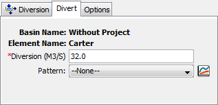
Figure 2. Specifying the constant diversion flowrate without using the optional annual adjustment pattern.
An annual adjustment pattern is optional. Without a specified annual pattern, the same diversion flowrate is used for every time interval in the simulation. When a pattern is specified, the diversion value is multiplied by the percentage found in the annual pattern for each time interval in the simulation. The annual pattern provides a percentage that varies throughout the year. The percent annual pattern must be defined in the paired data manager before it can be used in the source element.
Inflow Function Divert
This method uses a functional relationship between inflow and diversion flow to determine the amount of flow to divert from the channel. The range of inflows specified in the function should cover the complete range of total inflow from upstream elements. Usually the first inflow in the function should be zero. The last inflow should be greater than the maximum anticipated inflow to the element. Diversion flow is the dependent variable and must be specified for each corresponding inflow value. The determination of the correct diversion flow for a specified inflow depends on how the diversion operates. Generally you must compute the diversion for each inflow value using knowledge of the lateral weir, pump station, or other structure that is represented by the diversion element. The Component Editor is shown in Figure 3.
Select the inflow-diversion function from the list of available choices. The inflow-diversion function must be specified in the paired data manager before it can be selected in the component editor.
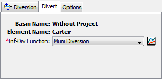
Figure 3. The inflow-diversion function divert editor.
Lateral Weir Divert
The only method currently available for computing flow over the lateral weir is the broad-crested spillway method. Flow depth in the channel is computed using a rating curve. It is assumed to be level with a uniform head along the length of the weir computed using the rating curve. Tailwater is similarly computed using a rating curve that represents the characteristics of the area where the weir discharges the diverted flow. The Component Editor is shown in Figure 4.
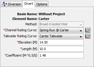
Figure 4. The lateral weir divert method editor.
A rating curve must be selected for the channel. The curve should give the stage for the entire range of inflows that will occur during a simulation. The curve must be monotonically increased. It must be defined in the paired data manager before it can be selected.
Optionally, a rating curve may be entered for tailwater. The curve should give the tailwater stage in the area where the diverted flow is discharged. It is used to automatically account for submergence of the weir. The curve must be monotonically increasing. It must be defined in the paired data manager before it can be selected. If the optional rating curve is not specified, then flow over the weir is computed assuming no tailwater influence.
The crest elevation of the weir must be specified. This should be measured in the same vertical datum as the paired data functions defining the rating curves.
The length of the weir must be specified. This should be the total width through which water passes.
The discharge coefficient accounts for energy losses as water enters the weir, flows over the weir, and then exits. Depending on the exact shape of the weir, typical values range from 1.10 to 1.66 in System International units (2.0 to 3.0 US Customary units).
Pump Station Divert
The pump station divert method is designed to represent one or more pump units extracting water from a channel and discharging it into a canal or other open channel. Flow depth in the channel is computed using a rating curve, then compared with the operating elevations for the pump. Tailwater is similarly computed using a rating curve that represents the characteristics of the area where the pump discharges the diverted flow. The Component Editor is shown in Figure 5.
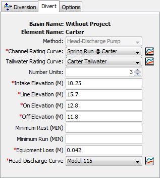
Figure 5. The pump station divert method editor.
A rating curve must be selected for the channel. The curve should give the stage for the entire range of inflows that will occur during a simulation. The curve must be monotonically increased. It must be defined in the paired data manager before it can be selected. You can press the paired data button next to the selection list to use a chooser. The chooser shows all of the available elevation-discharge functions in the project. Click on a function to view its description.
Optionally, a rating curve may be entered for tailwater. The curve should give the tailwater stage in the area where the diverted flow is discharged. It is used to automatically account for submergence of the pump discharge line. The curve must be monotonically increasing. It must be defined in the paired data manager before it can be selected. If the optional rating curve is not specified, then discharge from the pump is computed assuming no tailwater influence on the discharge line.
The number of identical units must be specified. This allows data to be entered only once when there are multiple pump units with exactly the same parameters.
The intake elevation defines the elevation in the reservoir pool where the pump takes in water. This should be measured in the same vertical datum as the paired data functions defining the storage characteristics of the reservoir.
The line elevation defines the highest elevation in the pressure line from the pump to the discharge point. This should be measured in the same vertical datum as the paired data functions defining the storage characteristics of the reservoir.
You must specify the elevation when the pump turns on. This should be measured in the same vertical datum as the paired data function defining the stage in the channel. Once the pump turns on, it will remain on until the stage in the channel drops below the trigger elevation to turn the pump off.
You must specify the elevation when the pump turns off. This should be measured in the same vertical datum as the paired data function defining the stage in the channel. This elevation must be lower than the elevation at which the pump turns on.
The specification of a minimum rest time is optional. If it is used, once a pump shuts off it must remain off the specified minimum rest time even if the reservoir pool elevation reaches the trigger elevation to turn the pump on.
The specification of a minimum run time is optional. If it is used, once a pump turns on it must remain on the specified minimum run time even if the reservoir pool elevation drops below the trigger elevation to turn the pump off. The only exception is if the pool elevation drops below the intake elevation, then the pump will shut off even though the minimum run time is not satisfied.
The equipment loss includes all energy losses between the intake and discharge points. These losses are are sometimes called static losses because the do not change very much even as the water surface elevation in the channel fluctuates. Components of the loss include entrance losses to the suction line, losses in the pump itself, pipe friction losses, bend losses in the line, and exit losses at the end of the discharge line. This loss is added to the dynamic head to determine the total head against which the pump must operate.
The head-discharge curve describes the pumping capability of the pump as a function of the total head. The total head is the sum of the equipment loss and the dynamic head. The dynamic is head is first estimated as the difference between the water surface elevation in the channel and the line elevation. If the water surface elevation is above the line elevation, then the estimated value will be zero. Secondarily, the estimate is adjusted for tailwater submergence. This second stage is only necessary if an optional tailwater rating curve is specified. When specified, the tailwater water surface elevation is compared to the line elevation. If the tailwater exceeds the line elevation, then the depth of submergence over the line elevation is added to the initial estimate of the dynamic head. The head-discharge curve is used to calculate the diverted flow given the calculated total head. A curve must be defined as an elevation-discharge function in the paired data manager before it can be selected for a pump in the diversion element. You can press the paired data button next to the selection list to use a chooser. The chooser shows all of the available elevation-discharge functions in the project. Click on a function to view its description.
Specified Flow Divert
The specified flow diversion method is designed for situations where the flow diverted from the channel is measured with a flow gage. Alternately, it can be used if the diversion flow is calculated externally from the program. In either case, the user may enter a time-series of discharges to be diverted from the channel. If the specified diversion discharge exceeds the total inflow to the diversion, then diversion will be limited to the inflow volume. The Component Editor is shown in Figure 6.
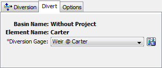
Figure 6. The specified flow divert method.
The time-series discharge gage representing the diversion flows must be defined in the time-series manager before it can be used in the diversion element, as shown in Figure 6. Selecting the correct gage is performed on the Component Editor for the diversion element. Access the Component Editor by clicking the diversion element icon on the "Components" tab of the Watershed Explorer. You can also access the Component Editor by clicking on the element icon in the basin map, if the map is currently open.