Download PDF
Download page Basin Model Properties.
Basin Model Properties
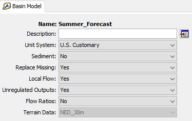
There are a number of properties for basin models that are selected on the Component Editor, as shown in Figure 1. These properties control configuration settings for the basin model itself or for all hydrologic elements within the basin model. Access the Component Editor from the Watershed Explorer on the "Components" tab by clicking on a basin model icon.
Local Flow
Local flow can be computed at junctions. Local flow is defined as the sum of all subbasin and source outflows entering a junction. The subbasin and source elements must be connected directly to the junction. Any subbasin or source outflow that moves through a routing element is no longer considered local flow. When local flow is disabled, a junction element computes outflow as the sum of all inflow from any type of element. No local flow is computed. When local flow is enabled, a junction continues to compute outflow as the sum of all inflow. However, in addition to computing outflow, it additionally computes local flow (sum of subbasin and source elements). Enabling or disabling local flow is done in the Component Editor for the basin model, as shown above. Access the Component Editor from the Watershed Explorer on the "Components" tab by clicking on a basin model icon.
Unregulated Outputs
Unregulated outputs (flow, stage, water surface elevation, velocity, etc) can be computed at all elements downstream of regulating structures. Within HEC-HMS, reservoir and diversion elements are considered regulating structures. Unregulated outputs are produced by setting the outflow of a regulating structure equal to the computed inflow. In this way, translation, attenuation, diversion, and/or other regulating effects are removed.
The Unregulated Outputs option is accessed within the Component Editor for the basin model, as shown above. When the Unregulated Outputs option is disabled, no changes to the computations will be made. When the Unregulated Outputs option is enabled, a second iteration will be made through all basin model computations. Within this second iteration, the routing method for all reservoir and diversion elements will be set to None. Additional time series will then be written to disk and made available within the Results tab. Unregulated outputs can be generated within all simulation types except for Optimization Trials.
Flow Ratio
Flow ratios can be used to increase or decrease the computed flow by a fixed ratio; they can only be applied to subbasin and source elements. Once the flow ratios are turned on, each subbasin and source can have a separate ratio, or no ratio. It is not necessary to enter a ratio for every element in order to have a ratio at one element. The ratio 1.0 is used if no ratio is specified. The calculations for computing outflow proceed normally according to the method choices and parameter data for each element. At the conclusion of normal processing, the flow ratio is applied to produce the final outflow.
Flow ratios are enabled or disabled in the Component Editor for the basin model, as shown above. After disabling the flow ratios, any ratios specified for subbasin and source elements in the basin model are removed and cannot be retrieved again or undeleted. The actual flow ratio is specified in the Component Editor for the element on the "Options" tab. Access the editor from the Watershed Explorer on the "Components" tab by clicking on the element icon. The last tab in the Component Editor is the "Options" tab. The flow ratio field is disabled when flow ratios are disabled in the basin model. The field becomes enabled when flow ratios are enabled in the basin model. The flow ratio field is never enabled for elements other than subbasins and sources.
Missing Flow
Missing inflow data for an element can be set to zero. Under some conditions it may be possible for source or subbasin elements to produce outflow with missing values. Downstream routing elements generally cannot process missing data. When missing flow data is not replaced, any element that encounters missing inflow data will halt a simulation with an error message. When missing flow data is replaced, the missing inflow data is set to zero and a message is generated that indicates how many values were missing. Processing in the routing element proceeds normally after any missing inflow data is set to zero. Setting the action to take with missing inflow data is done on the Component Editor for the basin model, as shown above.
Unit System
Each basin model must be in either United States customary units (sometimes called English units) or in system international units (also called metric units). All parameter data in a basin model must be in the same unit system. If you change the unit system, all data will be automatically converted to the new unit system. All time-series data, paired data, and gridded data referenced in a basin model will be in its own unit system. If necessary these referenced data are automatically converted to the unit system of the basin model during a simulation.
The unit system is designated within the Component Editor for the basin model, as shown above. Access the Component Editor by clicking the basin model icon on the "Components" tab of the Watershed Explorer. If you change the unit system, all data is automatically converted to the new selection.
Sediment
The movement of sediment in the watershed can be included as part of the hydrology of the basin model. When the sediment is disabled, no sediment processing will take place in the basin model. When the sediment is enabled, appropriate sediment simulation components are added to elements in the basin model. Subbasin elements include surface erosion and wash-off. Reach elements include erosion, deposition, and sediment transport. Reservoir elements include sediment settling and sediment transport. Source, junction, diversion, and sink elements pass sediment through the channel network.
Water Quality
Nutrient water quality (nitrogen and phosphorus) will be enabled within a future version of HEC-HMS.