Download PDF
Download page Flow Network.
Flow Network
The flow network is the skeleton that connects hydrologic elements together into a representation of the stream system in the watershed. Each link in the network is a one-way connector that takes outflow from an element and connects it as inflow to a downstream element. The connection information of the flow network along with the drainage area at each element is used to sort the elements in hydrologic order.
Moving Elements
Hydrologic elements are moved in the Basin Model Map window; they are moved the same way regardless of whether they are connected to a downstream element. To move an element, start by selecting the Arrow Tool from the toolbar. Next click the icon of the element you wish to move; it will become highlighted. Keep the mouse over the element and hold the left mouse button. Drag the mouse until the element icon is in the desired location. Release the left mouse button to finalize the move.
Reach elements are often connected between two junctions or possibly between other element types. Reach elements must connect to the upstream and downstream element. If a reach is connected on both ends, it can only be moved by moving the upstream or downstream element. If a reach is not connected on one end, that free end can be moved. Click on the reach once with the mouse to select it. Move the mouse over the free end of the reach and click again with the left mouse button. A small blue box appears at the free end. Keep the mouse over that box and hold the left mouse button. Drag the mouse to move the free end of the reach. Release the left mouse button to finalize the new location for that end of the reach. If a reach is not connected on either end, the entire reach can be moved. Click on the reach once with the mouse to select it. Keep the mouse over the reach and hold the left mouse button. Drag the mouse to move the reach to a new location. Release the left mouse button to finalize the new reach location.
More than one element can be moved at a time. To move multiple elements, the user must select the elements that will be moved. You may select the elements one at a time. Begin by clicking the first element. Subsequently, hold the control key and click additional elements. A selected element can be unselected by holding the control key and clicking it again. You may also select elements by dragging a box while the arrow tool is selected. You could also select elements using the Select By Name… command on the Edit menu. After selecting all desired elements, use the arrow keys on the keyboard to move the elements. The elements will move one distance increment each time an arrow key is pressed. The elements can be moved in smaller distance increments by holding the control key while pressing the arrow keys.
Connecting and Disconnecting Elements
Hydrologic elements can be connected or unconnected from the network using two different methods. The first method uses the mouse in the Basin Model Map window. The second method is found on the Component Editor for the element.
To connect an element in the Basin Model Map window, start by selecting the Arrow Tool from the toolbar. Next move the mouse over the element you wish to connect to a downstream element, then press the right mouse button. A context menu is displayed which includes the Connect Downstream command. If the element is already connected, the command will not appear on the menu. After you click the Connect Downstream command, the cursor will change to cross hairs as shown in Figure 1. Move the mouse to position the cross hairs over the element to which you wish to connect. Once the mouse is positioned, press the left mouse button. A connection link will be shown between the upstream and downstream elements.
To disconnect an element in the Basin Model Map window, start by selecting the Arrow Tool from the toolbar. Next click the icon of the element you wish to disconnect from its downstream element; the element you click will become highlighted. Click the right mouse button to see a context menu that includes Delete Connection. If the element is not connected, the command will not appear. After you click the Delete Connection command, the connection link between the upstream and downstream element will be removed.
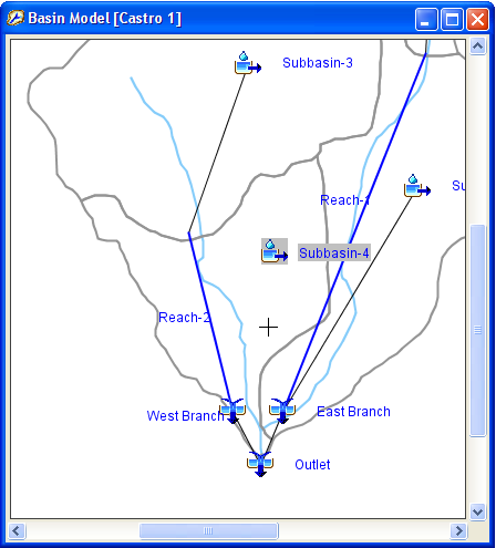
Figure 1. Preparing to connect the subbasin downstream to West Branch junction. The process was started by placing the mouse over Subbasin-4 and pressing the right-mouse button. Then the Connect Downstream command was selected. Note the mouse has changed to a cross hairs cursor for selecting the desired downstream element.
You can also create and delete connections from the Component Editor for the element (Figure 2). To access the Component Editor, click on the desired element in the Basin Model Map window, or on the "Components" tab of the Watershed Explorer. The Component Editor shows the downstream element. If the element is not connected to a downstream element, the selection list will show None as the selected element. To connect the element currently shown in the Component Editor, select an element on the list. Only elements that could potentially be downstream of the current element are shown. To disconnect the current element, change the selection in the list to the None selection.
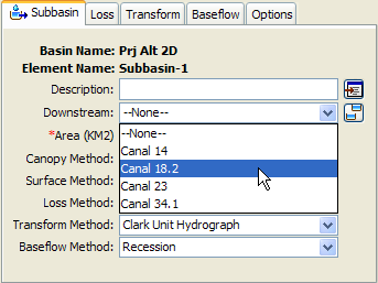
Figure 2. Selecting a downstream element using the subbasin component editor. The selection list shows all of the elements that can be downstream of the subbasin.
Hydrologic Order
Hydrologic order means that elements from the basin model are shown in order from the headwaters to the outlet. The key properties used to determine hydrologic order are the flow network connections and drainage area. From each element in the basin model it is possible for the program to automatically determine the downstream element, and the upstream elements. These connections create the basic structure of the network. The area entered for subbasins and sources is used to determine the drainage area for any other downstream element in the network. While area is optional in source elements for many purposes, the hydrologic order downstream of a source cannot be properly determined if the area is not specified. A simple basin model is shown in Figure 3, with the corresponding Watershed Explorer shown in Figure 4.
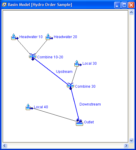
Figure 3. A simple basin model for demonstrating hydrologic order.
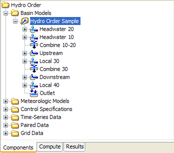
Figure 4. Watershed Explorer showing hydrologic order corresponding to the elements shown in Figure 3.
The hydrologic order shown in the Watershed Explorer is maintained automatically. Elements added to the basin model are automatically sorted into correct hydrologic order. When an element is connected to the flow network, or disconnected, the hydrologic order will be automatically updated to reflect the change. Any changes to area for a subbasin or source element will automatically update drainage areas throughout the flow network, and if necessary update the hydrologic order.
The hydrologic order is determined beginning from the outlet element. The outlet element is placed at the bottom of the element list shown in the Watershed Explorer. Next the drainage areas of the elements immediately upstream of the outlet are compared. The element with the smaller drainage area is placed closest to the outlet, and the element with the larger drainage area is placed furthest. The process of comparing the drainage areas of the upstream elements is then repeated element by element until all elements have been sorted. In the case shown in Figure 4, the drainage area of the "Headwater 20" subbasin is larger than the drainage area of the "Headwater 10" subbasin.
Some basin models have more than one outlet. When this is the situation, each outlet and its upstream elements are sorted as outlined above. A second level of sorting is then carried out using the drainage area of each outlet. The outlet with the largest drainage area appears at the bottom of the Watershed Explorer, with its upstream elements above it. The outlet with the smallest drainage area appears at the top of the Watershed Explorer, with its upstream elements above it.
In some situations the automatic sorting of hydrologic elements may not achieve the desired result. Manual adjustments may be made to the order, and the adjusted order is then maintained as the new hydrologic order. Two methods exist for making manual adjustments. The first option is to click on an element in the Watershed Explorer so that it is selected. Next, right click on the element and choose either the Move Up or the Move Down menu command, as shown in Figure 5. The selected element will be moved up or down one position in the element ordering. Repeated moves will be necessary in order to move the element up or down more than one position. You may also select a contiguous block of elements and move all of them up or down position in unison.
Any selected element in the Watershed Explorer can be moved several positions at once using the mouse. Start by clicking on an element to select it. Next, carefully position the mouse over the selected element and hold the left mouse button, and then drag the mouse. The shape of the cursor will change while you drag the element and you will also see an insertion, as shown in Figure 6. The insertion line shows where the element will be placed when you release the mouse button. Drag the mouse up or down over the other elements until you position the mouse where you want the element, and then release the button. The element will be moved to the new position in the hydrologic order.
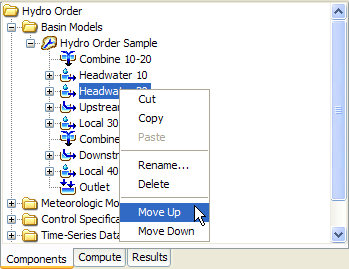
Figure 5. Manually moving an element in the hydrologic order using the right mouse menu.
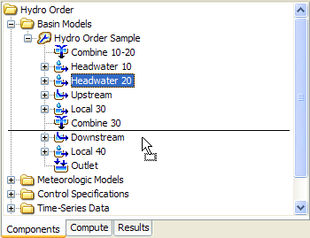
Figure 6. Manually moving an element in the hydrologic order by dragging it and dropping into position. The insertion line shows the drop location.
Global editors and simulation results shown throughout the program will display elements in hydrologic order, as shown in the Watershed Explorer. Hydrologic order will be used when the editor or result is first opened. However, each result window also includes a selection choice for switching between hydrologic order and alphabetic order.
Locking Element Locations
Moving elements is an important part of creating a basin model. It is usually not necessary to perform moves once all elements have been created and connected in the flow network. However, elements could be accidentally moved small distances then they are selected depending on the user's skill with a mouse and the sensitivity settings of the mouse hardware. You can lock element locations to avoid such accidental moves. Right click on a basin model node in the Watershed Explorer and choose the Lock Element Locations menu option (Figure 7). Choosing this option toggles between permitting element moves and locking the element locations to prevent moves. Once the locking is selected, it is no longer possible to move elements. Unselect the locking option if you wish to move elements.
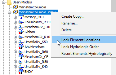
Figure 7. Lock element locations, icons, within the basin model map.
Locking Hydrologic Order
Sometimes the downstream connection of an element needs to be changed in the flow network. Other times it is necessary to add an element to the basin model. In these cases it is helpful to have the automatic hydrologic ordering of the elements. The remainder of the time it is not necessary to change the hydrologic ordering. In fact, if many manual adjustments have been made to the hydrologic ordering, the ordering should be preserved against accidental resorting or adjustment. You can lock the hydrologic order to avoid such accidental changes.
Right click on a basin model node in the Watershed Explorer and choose the Lock Hydrologic Order menu option (Figure 7). When the lock is disengaged, it is possible to resort the elements using the right mouse menu for the basin model in the Watershed Explorer. It is also possible to make manual adjustments using the right mouse menu for an element in the Watershed Explorer, or by dragging the element with the mouse. The ordering will also be updated as elements are added in the basin model, or downstream flow connections are changed.
When Lock Hydrologic Order is engaged, it is not possible to make any manual adjustments to the element order. Right mouse menus and mouse dragging will be disabled. Any elements added to the basin model will be put at the bottom of the element list. Elements will not move in the hydrologic order even if downstream flow connections are changed. You will need to turn off the locking in order to make any changes.