Download PDF
Download page Initial Conditions, Bed Materials, and Transport Parameters.
Initial Conditions, Bed Materials, and Transport Parameters
The Initial Conditions and Transport Parameters is the first tab in the Sediment Data editor and opens by default when the editor launches. From this editor the user can specify the transport function, sorting method, fall velocity method for the entire model. It is also used to specify sediment data for 1D cross-sections. However, if the model does not include cross-sections, then that information may be left empty.
Transport Function
Select a Transport Function from the drop-down box near the top of the editor. HEC-RAS 6.0 includes the following eleven transport functions:
- Ackers and White (Ackers and White 1973; Day 1980; Proffitt and Sutherland 1983)
- England and Hansen (Engelund-Hansen 1967)
- Laursen-Copeland formula (Laursen 1968)
- Meyer-Peter and Müller (1948)
- Toffaleti (1968)
- MPM-Toffaleti (Meyer-Peter and Müller 1948; Toffaleti 1968)
- Yang (sand and gravel eqns.)
- Wilcock and Crowe (2003)
- Soulsby-van Rijn (Soulsby 1997)
- van Rijn (1984a,b; 2007a,b)
- Wu et al. (2000)
Modeling Note – Transport Function Sensitivity: Sediment transport functions simulate non-linear transport processes and produce very different results. Model results are very sensitive to selected function. Carefully review the range of assumptions, hydraulic conditions, and grain sizes for which each method was developed. Select the method developed under conditions that most closely represent the system of interest and calibrate results to actual bed change.
Note: Transport Function Sensitivity
Sediment transport functions simulate non-linear transport processes and produce very different results. Model results are very sensitive to selected function. Carefully review the range of assumptions, hydraulic conditions, and grain sizes for which each method was developed. Select the method developed under conditions that most closely represent the system of interest and calibrate results to actual bed change.
Sorting Method
Transport functions compute transport potential without accounting for availability. The bed Sorting Method (sometimes called the mixing or armoring method) keeps track of the bed gradation which HEC-RAS uses to compute grain-class specific transport capacities and can also simulate armoring processes which regulate supply. The Sorting Method drop down menu in the Sediment Data editor only applies to 1D sediment transport. The 2D sediment transport model always uses a method similar to the Active Layer method for 1D except that it can have any arbitrary number of layers. The active layer thickness is set equal to the D90 by default or a factor of the D90.
Note: Sorting Method Model Sensitivity
Sediment transport results can be as sensitive to the sorting method parameters selected as the transport function.
Fall Velocity Methods
The same sediment fall velocity formulas are available for 2D and 1D sediment transport. The options include:
- Rubey (1933)
- Toffaleti (1968)
- Van Rijn (1993)
- Report 12 (Default method in HEC-6)
- Dietrich (1982)
- Soulsby (1997)
- Wu and Wang (2006)
The fall velocity formula used to compute free particle settling velocity for both cohesive and noncohesive sediments. Depending on the concentration and whether the user has selected flocculation, cohesive sediments may also settle as flocs. Hindered settling of noncohesive particles may also be simulated if selected by the user. In general, the fall velocity formula should not used as a model calibration parameter for morphology change, since the results are not very sensitive to the formula. Preference for the formulas is generally based on the transport formula used, the range of grain classes, and/or the parameters utilized by the fall velocity formulas. For example, the Wu and Wang formula takes into account the particle shape.
Bed Gradations
Bed gradations are specified in the same manner as for 1D models. Instead of requiring users to input gradations for each cell individually, HEC-RAS uses a Bed Gradation Template concept similar to that in the Channel Modification Editor. Sediment Bed Material Types are defined in a Sediment Bed Material Layer in RAS Mapper. The Sediment Bed Material Types are regions defined as polygons in RAS Mapper in a Sediment Bed Material Layer. The polygons can be overlapping to override regions. Sediment Bed Material Layer Types are the associated to Bed Gradation Templates, Non-erodible Surfaces, or Bed Layer Groups within the 2D Bed Gradations (Beta) tab of the Sediment Data editor. Bed Layer Groups consist of one or more bed layers. Each layer is assigned a Bed Gradation Template or a Non-erodible Surface. The connectivity between these elements utilized for specifying the sediment bed material are described in the schematic below.
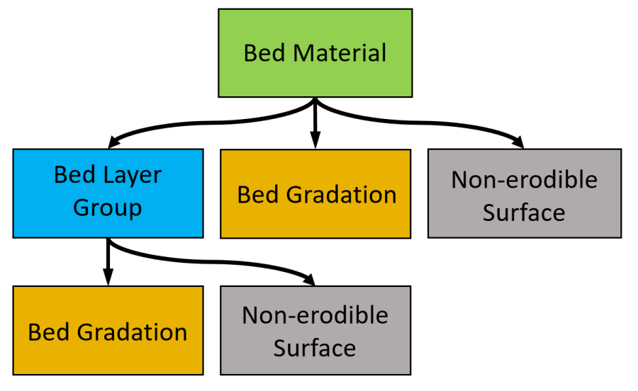
Figure 1. Bed Gradation Template editor.
Non-erodible surfaces are surfaces such as bedrock or structures which cannot be eroded. Non-erodible surfaces may be associated with a Sediment Bed Material are specified within a Bed Layer Group. Non-erodible surfaces are specified at computational cells and are not enforces at computational faces.
Defining Bed Material Layers in RAS Mapper
Users will associate bed gradations, layer groups, or non-erodible surfaces with Sediment Bed Material Layers defined in RAS Mapper. In order to define gradations in the sediment editor, you must define Sediment Bed Material Layers in Mapper first.
Sediment Bed Material Layers are independent of specific model geometries or terrains. Like n-value Layers or Land Cover Layers (see 2D Hydraulic Manuals). Create new Sediment Bed Material Layers by right clicking on the Map Layer node in RAS Mapper.
To Define Bed Material Layers, follow these five steps:
- Create a New/Empty RAS Layer
- Import or Draw Polygons in the Created RAS Layer
- Give the Polygon Classifications Sediment Material Names that will show up in the Sediment Editor
- Go to Manage Geometry Associations and associate the Bed Material Layers with geometry files
- Associate each Bed Material Classification with a bed gradation, bed layers, or define it as a non-erodible surface, in the 2D sediment editor.
Defining these bed material layers have two main workflows, which are not mutually exclusive. Users will generally import a pre-existing shape file or draw overlapping polygons. Often users will do both, importing a base bed material shape file, but then drawing in channel features, sand bars, and/or non-erodible features on top of them as new layers.
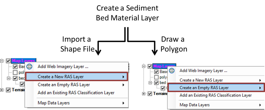
Figure 2. Crating a Bed Material Layer in RAS Mapper.
The Sediment Bed Material Layer will show up under the Map Layers tree in RAS Mapper.
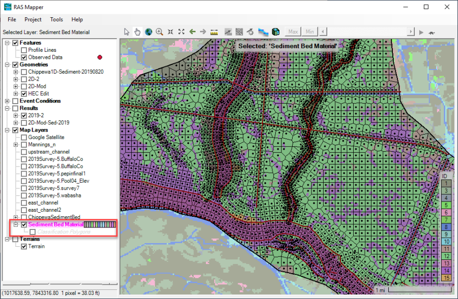
Figure 3. Sediment Bed Material Layer underlying a 2D mesh and in the RAS Mapper tree under Map Layers.
Whether you create your Sediment Bed Material Layer by importing a shape file, creating polygons, or both, there are two additional steps before the bed materials are ready for the sediment model.
Modeling Note - HEC-RAS Uses the Gradation at the Cell Computation Point
Sediment Bed Material Layers can be more detailed than the mesh. If a 2D cell includes multiple sediment bed material layers, HEC-RAS uses the material type associated with the computation point.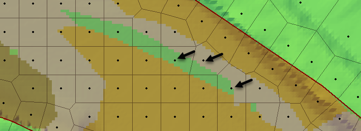
RAS Mapper will create a Classification Polygons node under your map layer and will add a feature to the geo-referenced database for each polygon you import or create. You will have to give each of these polygons a (preferably descriptive) name which will show up in the sediment editor, where you will associate the polygon(s) that share this classification with a Bed Material or Bed Layer Group.
Name the layer classifications by right clicking on the Classification Polygons node (in editable mode ![]() ) and selecting Layer Properties. Then select the Features tab and give each of the Layer Classifications a Name that will show up in the Sediment Data editor.
) and selecting Layer Properties. Then select the Features tab and give each of the Layer Classifications a Name that will show up in the Sediment Data editor.
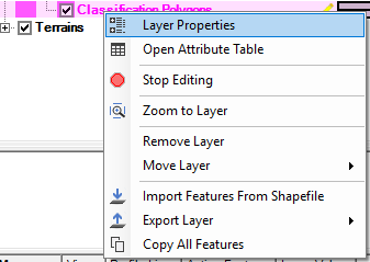
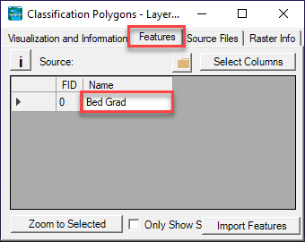
Figure 4. Give the layer classifications names that will show up in the sediment editor under Layer Properties.
When the Sediment Bed Material Layer and Classifications are complete, Stop Editing and save.
Before these layers and classifications become available in the Sediment Data editor, however, they must be associated with a geometry file. Just like n-values, Land Cover, and Terrains must be associated with a geometry file, Sediment Bed Material Layer Groups must be matched to one-or-more geometries to connect the Mapper classifications to the other files in HEC-RAS.
Right Click on the Geometries node in RAS Mapper and Select Manage Geometry Associations… 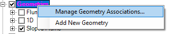
Select the Sediment Bed Material Layer that goes with each Geometry.
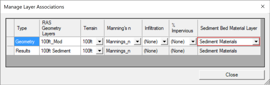
Figure 5. RAS Mapper Manage Layer Associations editor.
It is worth noting, that this associates the Bed Gradation Layers with the geometry, not the sediment file. Sediment files depend on geometry files for some of their data structures (e.g. cross sections in 1D). The sediment file will inherit the bed gradation layers and classifications from the active geometry file.
These layer classifications will become available in the 2D Sediment tab of the Sediment Data Editor (see the 2D gradation selection section).
Bed Gradation Templates
Bed Gradation Templates contain the sediment grain class sizes, grain fractions by weight, and optionally bulk cohesive parameters. Users define sediment Bed Gradations Templates in a database with no spatial data. They can be considered simply as a database of different sediment types. In many applications, Bed Gradation Templates will correspond to individual bed samples taken in the project. Templates are created and edited by pressing the Define/Edit Bed Gradation button, which will launch the dialog depicted in the figure below.
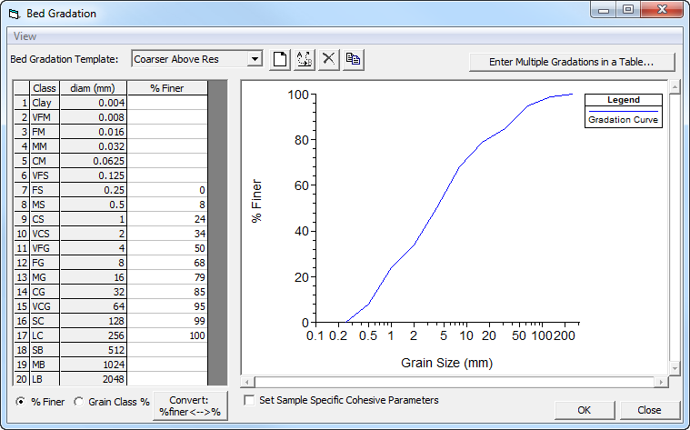
Figure 6. Bed Gradation Template editor.
Multiple bed gradations may be entered for 2D sediment models in the same as for 1D sediment models.
To create a Bed Gradation Template, first create a new bed gradation template by selecting the New Bed Gradation Sample button: and entering a name for the sample. (Alternatively, data for several different samples can be entered at once by clicking on the ![]() button and entering the data in the Multiple Bed Gradation Table.
button and entering the data in the Multiple Bed Gradation Table.
The gradation of the bed sample can be input in either of two forms by toggling between the radio buttons at the bottom of the form:
• % Finer: % Finer defines the sample using as a cumulative bed gradation curve with percent finer defined by the upper bound of each grain class. The diameter listed for each grain class is the upper bound of that grain class and values should be entered as percent values. (e.g. since this is specified in Percent Finer, 50% should be input as 50 and NOT as 0.5)
• Grain Class Fraction/Weight: the sample fraction of each grain class is specified. These values will be normalized so values do not have to add up to one or 100% and can be input as simple masses if preferred. (e.g. if 20% of the sample is fine sand, input the value 0.2 or 20 as long as the rest follow that convention). The upper and lower bound grain diameter is associated with each grain class to delineate the range of the class.
Bed Layer Groups
User specified Bed Layer Groups allow the user to specify vertical bed layers with different bed gradations and different bulk properties. Bed Layer Groups are specified by selecting the button ![]() in the main Sediment Data editor which will open the Define Gradation Layers editor (see the figure below).
in the main Sediment Data editor which will open the Define Gradation Layers editor (see the figure below).
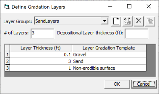
Figure 7. Example of a Bed Layer Group definition in the Define Gradation Layers editor.
In HEC-RAS 2D sediment transport, the depositional layer thickness is not utilized. The parameter is only utilized for 1D sediment transport.
The layer thickness specified for non-erodible surfaces is not actually used. Bed gradations are specified for each computational cell. Faces do not have bed gradations and only bed elevations. All subareas within a cell have the same Sediment Bed Material. Therefore, if a Bed Layer Groups is assigned to a cell, the bed layers will be at different elevations for the different subareas. For example, the figure below shows a computational which has been assigned a Bed Layer Group three layers. In the example below, the cell has three subareas. The bed layers have the same thickness in each subarea but start at a different elevation.
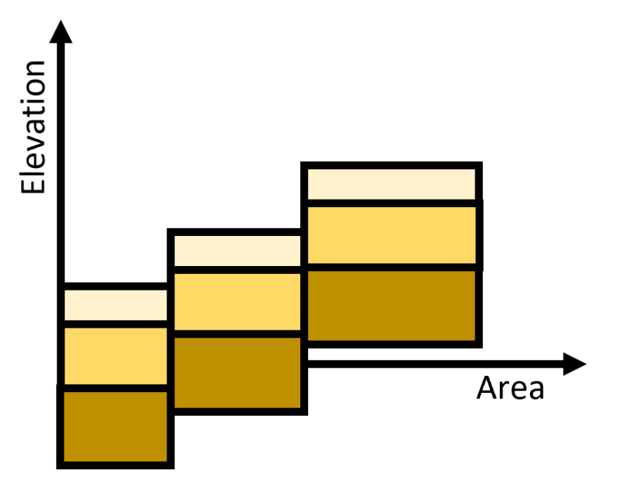
Figure 8. Example of a Bed Layer Group assigned to a computational cell.