Download PDF
Download page Coefficient of Discharge.
Coefficient of Discharge
The coefficient of discharge, as defined by Matthai and used in this model, is a function of bridge geometry and flow characteristics. Matthai's report presents detailed instructions for computing the coefficient of discharge for the four most common types of bridge openings. It is not practical to reproduce that entire report herein, but the following paragraphs summarize the procedures as adapted to this model. All of the key figures from Matthai's report, the tabular values and equations used to determine the coefficient of discharge, and a discussion of the minor modifications made to Matthai's procedures are presented in this appendix. Bridge openings are classified as one of four different types depending upon characteristics of embankment and abutment geometry. Regardless of opening type, the first step is to determine a base coefficient of discharge, C', which is a function of (1) a channel contraction ratio and (2) a ratio of flow length through the bridge, L, to the bridge opening width, b. The channel contraction ratio is
| 1) | \displaystyle m=1- \frac{K_q}{K_1} |
Where Kq is the conveyance of a portion of the approach section (based on projecting the bridge opening width up to the approach section) and K1 is the total conveyance of the approach section. The definition of the L and b terms for the length ratio depends upon the opening type. The definition sketches below define these terms for each opening type. The final coefficient of discharge, C, is computed by multiplying C' by a series of adjustment factors to account for variations in geometry and flow from the base conditions used to derive C'. The number of parameters for which adjustment factors are required depends partially upon the opening type. Following is a summary description of the opening types and the adjustment factors that are unique to each:
- Type 1 openings have vertical embankments and vertical abutments with or without wingwalls. The discharge coefficient is adjusted for the Froude number (kF) and also for wingwall width (kw) if wingwalls are present or for entrance rounding (kr) if there are no wingwalls.
- Type 2 openings have sloping embankments and vertical abutments and do not have wingwalls. The discharge coefficient is adjusted on the basis of the average depth of flow at the abutments (ky).
- Type 3 openings have sloping embankments with spill through abutments. The discharge coefficient is adjusted on the basis of entrance geometry (kx).
- Type 4 openings have sloping embankments, vertical abutments, and wingwalls. The discharge coefficient is adjusted depending upon the wingwall angle (kθ).
In addition to the above adjustment factors, which are dependent upon opening type, there are adjustment factors for piers or piles (kj) and spur dikes (ka, kb, kd) that may be applied to all opening types. The relationships used to compute all of the above adjustment factors are shown below.
Figures D-4 through D-7 are definition sketches of the four types of openings for which Matthai defined the coefficient of discharge. Figures D-8 through D-18 are the relationships defining the base coefficient of discharge and the factors used to adjust for nonstandard conditions. Except for type 1 openings, different curves are required for different embankment slopes. Most of these relationships are incorporated into HEC-RAS in the form of digitized values. The digitized values are shown in tabular form at the end of this appendix. Table D-1 cross references the figures and tables pertaining to the base coefficient of discharge. Table D-2 cross references those figures and tables pertaining to the various adjustment factors.
Generally each of the relationships are incorporated into HEC-RAS in the form of three arrays. Two one dimensional arrays contain values of the two independent variables (the abscissa of the relationship and the family of curves), and a two dimensional array contains the corresponding values of the dependent variable. Exceptions to this form of representation are discussed in the following paragraphs.
The type 1 opening Froude number adjustment (fig. D.8(b)) is adequately expressed in equation form as:
| 2) | k_F =0.9+0.2F \; \;(for 0.0 \leq F \leq 0.5) |
and
| 3) | k_F =0.82+0.36F \; \; (for F > 0.5) |
Where F is the Froude number with an arbitrary upper limit of F = 1.2 for the adjustment. The average depth adjustment for a type 3 opening with 2 to 1 embankment slope is determined by the following equations:
| 4) | k_y =1.00+0.3y \; \;(for 0.0 \leq y \leq 0.20) |
and
| 5) | k_y =1.02+0.2 \overline{y} \; \;(for \overline{y} > 0.2) |
where \displaystyle \overline{y} = \frac{y_a + y_b}{2b} with \overline{y} =0.30 as an upper limit.
The type 4 opening wing wall adjustment factor, kθ, is computed using slopes of the family of curves (figs. D-15 and D-16). The equation for specified m-values is:
| 6) | k_{\theta} =1.0+(WW-30)Sk_{\theta} |
Where WW is the wing wall angle and Skθ is the appropriate slope from tables D-16 or D-18. kθ is obtained by interpolation for intermediate m-values.
Certain adjustments presented by Matthai were not incorporated into the WSPR0 bridge methodology. The skew adjustment was omitted because WSPR0 always computes the flow area normal to the flow for skewed bridge openings. An adjustment for submerged flow was also omitted because the FHWA methodology is used to compute pressure flow when girders are significantly submerged. The Froude number adjustment for type 4 openings with 2 to 1 embankment slope was intentionally omitted for reasons of consistency. There is no similar adjustment for type 4 openings with 1 to 1 embankment slopes, and the adjustment is rather minor. Matthai also applied an adjustment for eccentricity, which is a measure of unequal conveyances on left and right overbanks of the approach section. This factor was not included in WSPR0 on the bases that (1) it is a very minor adjustment, and (2) the effective flow length accounts for conveyance distribution.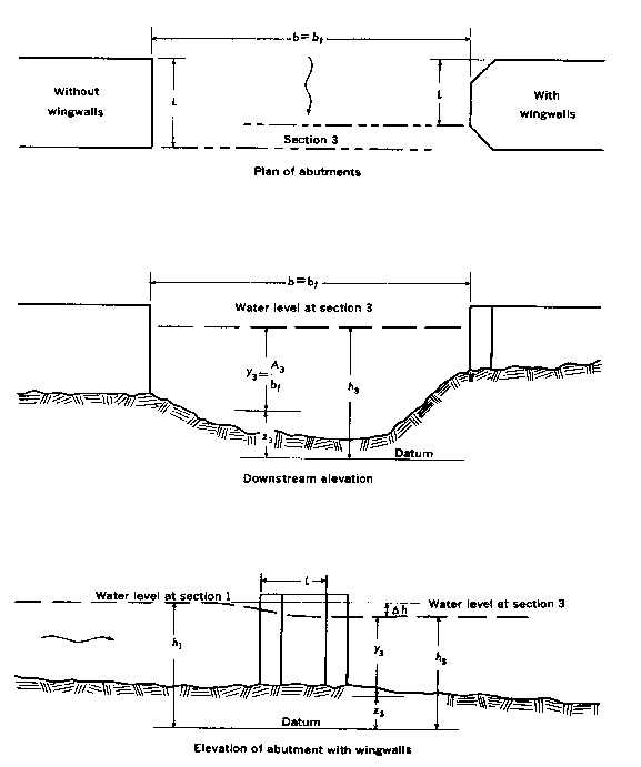
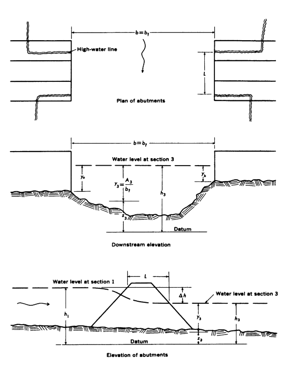
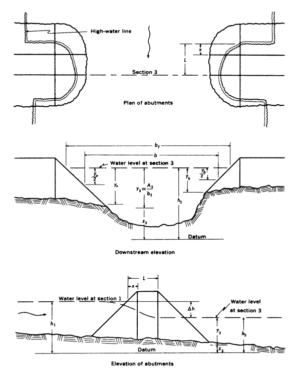
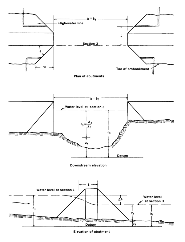
Table D-1 Cross-reference of Figures and Tables pertaining to the base coefficient of discharge.
Type | Embankment | Figure | Table |
|---|---|---|---|
1 | D-8 | D-3 | |
2 | 1 to 1 | D-10 | D-6 |
3 | 1 to 1 | D-12 | D-10 |
4 | 1 to 1 | D-15 | D-15 |
Table D-2 Cross-reference of Figures and Tables pertaining to adjustment factors
Type | Embankment | Adjustment | Figure | Table |
|---|---|---|---|---|
1 | Entrance Rounding | D-8 | D-4 | |
2 | 1 to 1 | Average Depth | D-10 | D-7 |
3 | 1 to 1 | Entrance Geometry | D-12 | D-11 |
4 | 1 to 1 | Wingwalls | D-15 | D-16 |
All | Piers or Piles | D-17 | D-19, D-20 |
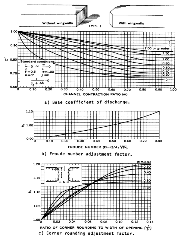
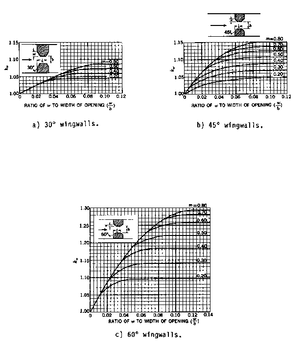

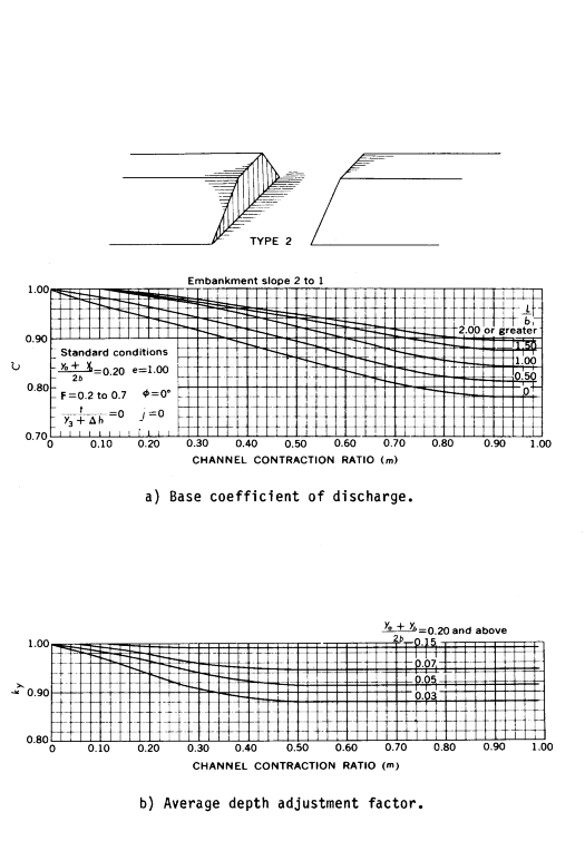

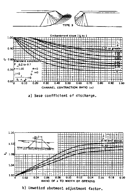
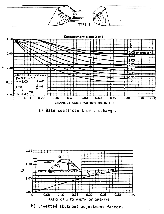
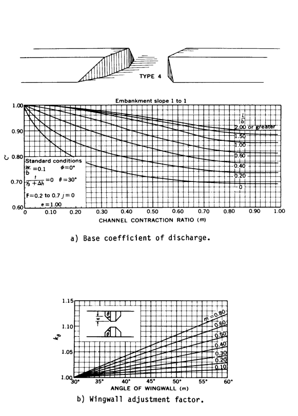
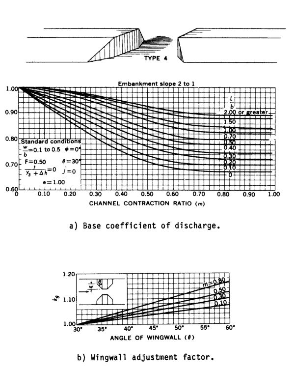
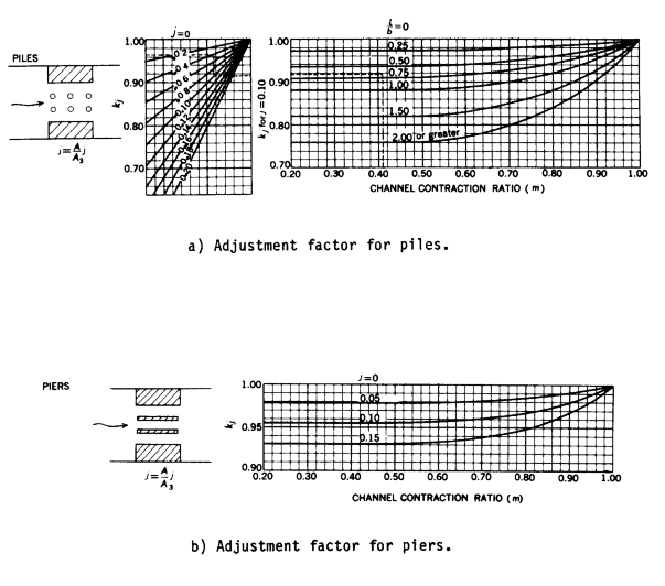
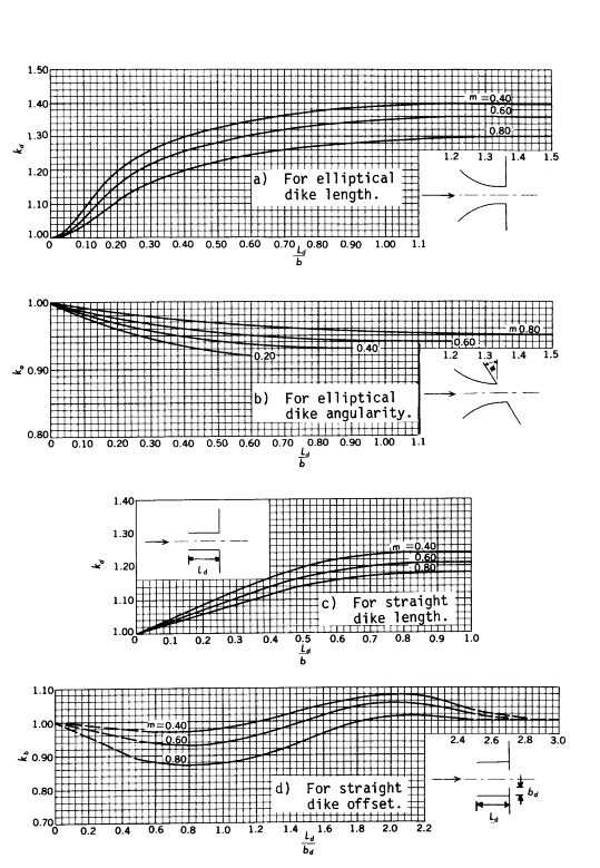
Table D-3 Base coefficient of discharge, C', for type 1 opening, with or without wing walls
m | ||||||
|---|---|---|---|---|---|---|
0.0 | 0.1 | 0.3 | 0.5 | 0.8 | 1.0 | |
0.0 | 1.00 | 0.83 | 0.745 | 0.70 | 0.67 | 0.67 |
0.2 | 1.00 | 0.92 | 0.81 | 0.74 | 0.685 | 0.685 |
0.4 | 1.00 | 0.95 | 0.86 | 0.755 | 0.71 | 0.71 |
L/b 0.6 | 1.00 | 0.965 | 0.89 | 0.82 | 0.735 | 0.735 |
0.8 | 1.00 | 0.97 | 0.91 | 0.855 | 0.77 | 0.765 |
1.0 | 1.00 | 0.98 | 0.935 | 0.885 | 0.80 | 0.795 |
1.5 | 1.00 | 0.985 | 0.95 | 0.91 | 0.845 | 0.835 |
2.0 | 1.00 | 0.99 | 0.955 | 0.92 | 0.87 | 0.86 |
m is the channel contraction ratio.
L/b is the ratio of flow length to bridge-opening width.
Table D-4 Variation of adjustment factor, kr, for type 1 opening with entrance rounding
r/b | |||||||
|---|---|---|---|---|---|---|---|
0.01 | 0.02 | 0.04 | 0.06 | 0.08 | 0.10 | 0.14 | |
0.1 | 1.06 | 1.07 | 1.07 | 1.07 | 1.07 | 1.07 | 1.07 |
0.2 | 1.04 | 1.08 | 1.11 | 1.11 | 1.11 | 1.11 | 1.11 |
m 0.4 | 1.03 | 1.05 | 1.09 | 1.12 | 1.14 | 1.15 | 1.16 |
0.6 | 1.02 | 1.04 | 1.08 | 1.12 | 1.15 | 1.17 | 1.18 |
0.8 | 1.02 | 1.04 | 1.08 | 1.12 | 1.16 | 1.18 | 1.20 |
1.0 | 1.02 | 1.04 | 1.08 | 1.12 | 1.16 | 1.18 | 1.22 |
r/b is the ratio of entrance rounding to bridge-opening width.
m is the channel contraction ratio.
Table D-5 Variation of adjustment factor, k0, for type 1 opening with wing walls (fig. D-9).
w/b | |||||||
|---|---|---|---|---|---|---|---|
0.01 | 0.02 | 0.04 | 0.06 | 0.08 | 0.10 | 0.14 | |
0.1 | 1.01 | 1.02 | 1.02 | 1.02 | 1.02 | 1.02 | 1.02 |
0.2 | 1.01 | 1.025 | 1.04 | 1.04 | 1.04 | 1.04 | 1.04 |
m 0.4 | 1.01 | 1.025 | 1.04 | 1.06 | 1.06 | 1.06 | 1.06 |
0.6 | 1.01 | 1.025 | 1.05 | 1.06 | 1.07 | 1.07 | 1.07 |
0.8 | 1.01 | 1.025 | 1.05 | 1.07 | 1.08 | 1.09 | 1.09 |
1.0 | 1.01 | 1.025 | 1.05 | 1.07 | 1.08 | 1.09 | 1.10 |
(a) 30o wing walls | |||||||
0.01 | 0.02 | 0.04 | 0.06 | 0.08 | 0.10 | 0.14 | |
0.1 | 1.00 | 1.01 | 1.01 | 1.02 | 1.02 | 1.02 | 1.02 |
0.2 | 1.01 | 1.02 | 1.04 | 1.04 | 1.05 | 1.05 | 1.05 |
m 0.4 | 1.03 | 1.05 | 1.07 | 1.08 | 1.09 | 1.09 | 1.09 |
0.6 | 1.03 | 1.06 | 1.10 | 1.11 | 1.12 | 1.12 | 1.12 |
0.8 | 1.03 | 1.06 | 1.11 | 1.13 | 1.15 | 1.15 | 1.15 |
1.0 | 1.03 | 1.06 | 1.11 | 1.13 | 1.15 | 1.16 | 1.17 |
(b) 45o wing walls | |||||||
0.01 | 0.02 | 0.04 | 0.06 | 0.08 | 0.10 | 0.14 | |
0.1 | 1.02 | 1.04 | 1.05 | 1.05 | 1.05 | 1.05 | 1.05 |
0.2 | 1.04 | 1.07 | 1.09 | 1.10 | 1.10 | 1.10 | 1.10 |
m 0.4 | 1.04 | 1.09 | 1.15 | 1.18 | 1.18 | 1.18 | 1.18 |
0.6 | 1.04 | 1.09 | 1.15 | 1.21 | 1.24 | 1.25 | 1.26 |
0.8 | 1.04 | 1.09 | 1.15 | 1.22 | 1.26 | 1.28 | 1.29 |
1.0 | 1.04 | 1.09 | 1.15 | 1.22 | 1.26 | 1.28 | 1.32 |
(c) 60o wingwalls
w/b is the ratio of wing wall width to bridge-opening width.
Table D-6 Base coefficient of discharge, C', for type 2 opening, embankment slope 1 to 1
m | ||||||
|---|---|---|---|---|---|---|
0.0 | 0.1 | 0.3 | 0.5 | 0.8 | 1.0 | |
0.0 | 1.00 | 0.92 | 0.845 | 0.805 | 0.755 | 0.745 |
0.2 | 1.00 | 0.955 | 0.88 | 0.83 | 0.775 | 0.765 |
0.4 | 1.00 | 0.97 | 0.91 | 0.85 | 0.795 | 0.79 |
L/b 0.6 | 1.00 | 0.975 | 0.925 | 0.87 | 0.81 | 0.805 |
0.8 | 1.00 | 0.98 | 0.94 | 0.895 | 0.835 | 0.825 |
1.0 | 1.00 | 0.985 | 0.95 | 0.91 | 0.855 | 0.845 |
1.5 | 1.00 | 0.988 | 0.96 | 0.93 | 0.885 | 0.88 |
2.0 | 1.00 | 0.99 | 0.965 | 0.94 | 0.905 | 0.90 |
m is the channel contraction ratio.
L/b is the ratio of flow length to bridge-opening width.
Table D-7 Variation of adjustment factor, ky, for type 2 opening, embankment slope 1 to 1
(see fig. D-10).
\displaystyle \frac{y_a + y_b}{2b} | m | |||||
|---|---|---|---|---|---|---|
0.0 | 0.2 | 0.4 | 0.7 | 1.0 | ||
0.03 | 1.00 | 0.94 | 0.895 | 0.86 | 0.86 | |
0.05 | 1.00 | 0.97 | 0.93 | 0.88 | 0.88 | |
0.07 | 1.00 | 0.985 | 0.955 | 0.91 | 0.91 | |
0.10 | 1.00 | 0.995 | 0.98 | 0.94 | 0.94 | |
0.15 | 1.00 | 1.00 | 1.00 | 0.98 | 0.98 | |
m is the channel contraction ratio.
(ya + yb)/2b is the ratio of average depth at the abutments to bridge-opening width.
Table D-8 Base coefficient of discharge, C', for type 2 opening, embankment slope 2 to 1
(see fig. D-10)
m | ||||||
|---|---|---|---|---|---|---|
0.0 | 0.1 | 0.3 | 0.5 | 0.8 | 1.0 | |
0.0 | 1.00 | 0.965 | 0.915 | 0.86 | 0.79 | 0.78 |
0.2 | 1.00 | 0.97 | 0.925 | 0.87 | 0.80 | 0.79 |
0.4 | 1.00 | 0.98 | 0.935 | 0.89 | 0.81 | 0.80 |
L/b 0.6 | 1.00 | 0.99 | 0.95 | 0.90 | 0.83 | 0.82 |
0.8 | 1.00 | 0.995 | 0.96 | 0.91 | 0.845 | 0.83 |
1.0 | 1.00 | 1.00 | 0.97 | 0.925 | 0.855 | 0.84 |
1.5 | 1.00 | 1.00 | 0.975 | 0.94 | 0.89 | 0.875 |
2.0 | 1.00 | 1.00 | 0.98 | 0.95 | 0.905 | 0.895 |
m is the channel contraction ratio.
L/b is the ratio of flow length to bridge-opening width.
Table D-9 Variation of adjustment factor, ky, for type 2 opening, embankment slope 2 to 1
(see fig. D-11)
\displaystyle \frac{y_a + y_b}{2b} | m | |||||
|---|---|---|---|---|---|---|
0.0 | 0.2 | 0.4 | 0.7 | 1.0 | ||
0.03 | 1.00 | 0.935 | 0.89 | 0.88 | 0.88 | |
0.05 | 1.00 | 0.965 | 0.925 | 0.91 | 0.91 | |
0.07 | 1.00 | 0.975 | 0.95 | 0.945 | 0.945 | |
0.10 | 1.00 | 0.985 | 0.97 | 0.97 | 0.97 | |
0.15 | 1.00 | 0.99 | 0.99 | 0.99 | 0.99 | |
m is the channel contraction ratio
(ya + yb)/2b is the ratio of average depth at the abutments to bridge-opening width.
Table D-10 Base coefficient of discharge, C', for type 3 opening, embankment slope1 to 1
(see fig. D-12)
m | ||||||
|---|---|---|---|---|---|---|
0.0 | 0.1 | 0.3 | 0.5 | 0.8 | 1.0 | |
0.0 | 1.00 | 0.85 | 0.74 | 0.71 | 0.69 | 0.69 |
0.2 | 1.00 | 0.91 | 0.79 | 0.745 | 0.71 | 0.71 |
0.4 | 1.00 | 0.945 | 0.83 | 0.775 | 0.74 | 0.735 |
L/b 0.6 | 1.00 | 0.97 | 0.87 | 0.81 | 0.765 | 0.76 |
0.8 | 1.00 | 0.985 | 0.91 | 0.85 | 0.795 | 0.79 |
1.0 | 1.00 | 0.995 | 0.945 | 0.88 | 0.82 | 0.81 |
1.5 | 1.00 | 1.00 | 0.96 | 0.91 | 0.86 | 0.85 |
2.0 | 1.00 | 1.00 | 0.97 | 0.925 | 0.88 | 0.875 |
m is the channel contraction ratio.
L/b is the ratio of flow length to bridge-opening width.
Table D-11 Variation of adjustment factor, ky, for type 3 opening, embankment slope 1 to 1. (see fig. D-12).
x/b | ||||||
|---|---|---|---|---|---|---|
0.00 | 0.08 | 0.12 | 0.16 | 0.20 | 0.25 | |
0.0 | 1.00 | 1.09 | 1.13 | 1.14 | 1.14 | 1.14 |
L/b 0.2 | 1.00 | 1.11 | 1.155 | 1.16 | 1.16 | 1.16 |
0.5 | 1.00 | 1.135 | 1.19 | 1.20 | 1.20 | 1.20 |
x/b is the ratio of "unwetted" abutment length to bridge-opening width.
L/b is the ratio of flow length to bridge-opening width.
Table D-12 Base coefficient of discharge, C', for type 3 opening, embankment slope 1-1/2 to 1
(see fig. D-13).
m | ||||||
|---|---|---|---|---|---|---|
0.0 | 0.1 | 0.3 | 0.5 | 0.8 | 1.0 | |
0.0 | 1.00 | 0.885 | 0.76 | 0.715 | 0.70 | 0.70 |
0.2 | 1.00 | 0.92 | 0.80 | 0.75 | 0.725 | 0.72 |
0.4 | 1.00 | 0.945 | 0.84 | 0.78 | 0.75 | 0.745 |
L/b 0.6 | 1.00 | 0.97 | 0.88 | 0.815 | 0.77 | 0.765 |
0.8 | 1.00 | 0.99 | 0.915 | 0.85 | 0.805 | 0.80 |
1.0 | 1.00 | 1.00 | 0.945 | 0.88 | 0.83 | 0.825 |
1.5 | 1.00 | 1.00 | 0.955 | 0.905 | 0.87 | 0.87 |
2.0 | 1.00 | 1.00 | 0.965 | 0.92 | 0.885 | 0.885 |
m is the channel contraction ratio.
L/b is the ratio of flow length to bridge-opening width.
Table D- 13 Variation of adjustment factor, kx, for type 3 opening, embankment slope 1-1/2 to 1
(see fig. D-13).
x/b | ||||||
|---|---|---|---|---|---|---|
0.00 | 0.08 | 0.12 | 0.16 | 0.20 | 0.25 | |
0.0 | 1.00 | 1.055 | 1.085 | 1.09 | 1.095 | 1.10 |
L/b 0.2 | 1.00 | 1.065 | 1.10 | 1.105 | 1.11 | 1.115 |
0.5 | 1.00 | 1.08 | 1.11 | 1.12 | 1.125 | 1.13 |
x/b is the ratio of "unwetted" abutment length to bridge-opening width.
L/b is the ratio of flow length to bridge-opening width.
Table D-14 Base coefficient of discharge, C', for type 3 opening, embankment slope 2 to 1
(see fig. D-14).
m | ||||||
|---|---|---|---|---|---|---|
0.0 | 0.1 | 0.3 | 0.5 | 0.8 | 1.0 | |
0.0 | 1.00 | 0.90 | 0.78 | 0.72 | 0.70 | 0.70 |
0.2 | 1.00 | 0.92 | 0.81 | 0.755 | 0.72 | 0.72 |
0.4 | 1.00 | 0.94 | 0.845 | 0.785 | 0.75 | 0.75 |
L/b 0.6 | 1.00 | 0.96 | 0.875 | 0.81 | 0.78 | 0.78 |
0.8 | 1.00 | 0.985 | 0.91 | 0.845 | 0.81 | 0.81 |
1.0 | 1.00 | 1.00 | 0.94 | 0.87 | 0.845 | 0.84 |
1.5 | 1.00 | 1.00 | 0.95 | 0.905 | 0.875 | 0.87 |
2.0 | 1.00 | 1.00 | 0.96 | 0.92 | 0.895 | 0.89 |
m is the channel contraction ratio.
L/b is the ratio of flow length to bridge-opening width.
Table D- 15 Base coefficient of discharge, C', for type 4 opening, embankment slope 1 to 1
(see fig. D-15)
m | ||||||
|---|---|---|---|---|---|---|
0.0 | 0.1 | 0.3 | 0.5 | 0.8 | 1.0 | |
0.0 | 0.99 | 0.85 | 0.755 | 0.715 | 0.695 | 0.69 |
0.2 | 1.00 | 0.90 | 0.815 | 0.775 | 0.735 | 0.73 |
0.4 | 1.00 | 0.955 | 0.885 | 0.83 | 0.775 | 0.77 |
L/b 0.6 | 1.00 | 0.985 | 0.935 | 0.875 | 0.815 | 0.81 |
0.8 | 1.00 | 0.99 | 0.955 | 0.91 | 0.84 | 0.835 |
1.0 | 1.00 | 1.00 | 0.965 | 0.925 | 0.855 | 0.85 |
1.5 | 1.00 | 1.00 | 0.97 | 0.94 | 0.89 | 0.885 |
2.0 | 1.00 | 1.00 | 0.975 | 0.95 | 0.905 | 0.90 |
m is the channel contraction ratio.
L/b is the ratio of flow length to bridge-opening width.
Table D- 16 Slopes of family of curves for determining adjustment factor, k0, for wing wall
Angle for type 4 openings, embankment slope 1 to 1 (see fig. D-15).
m | Skθ |
|---|---|
0.1 | 0.00057 |
0.2 | 0.001 |
0.4 | 0.002 |
0.6 | 0.00343 |
0.8 | 0.00413 |
1.0 | 0.00483 |
Table D-17 Base coefficient of discharge, C', for type 4 opening, embankment slope 2 to 1
(see fig. D-16).
m | ||||||
|---|---|---|---|---|---|---|
0.0 | 0.1 | 0.3 | 0.5 | 0.8 | 1.0 | |
0.0 | 1.00 | 0.93 | 0.80 | 0.705 | 0.67 | 0.67 |
0.2 | 1.00 | 0.95 | 0.855 | 0.765 | 0.725 | 0.725 |
0.4 | 1.00 | 0.97 | 0.895 | 0.815 | 0.78 | 0.78 |
L/b 0.6 | 1.00 | 0.985 | 0.925 | 0.845 | 0.805 | 0.805 |
0.8 | 1.00 | 0.99 | 0.94 | 0.87 | 0.825 | 0.825 |
1.0 | 1.00 | 0.995 | 0.95 | 0.89 | 0.85 | 0.85 |
1.5 | 1.00 | 0.995 | 0.965 | 0.91 | 0.88 | 0.88 |
2.0 | 1.00 | 1.00 | 0.97 | 0.925 | 0.89 | 0.89 |
m is the channel contraction ratio.
L/b is the ratio of flow length to bridge-opening width
Table D-18 Slopes of family of curves for determining adjustment factor, k0, for wing wall
Angle for type 4 openings, embankment slope 2 to 1 (see fig. D-16).
m | Skθ |
|---|---|
0.1 | 0.00243 |
0.2 | 0.00283 |
0.4 | 0.00373 |
0.6 | 0.00467 |
0.8 | 0.00557 |
1.0 | 0.00667 |
Table D-19 Adjustment factor, ki for piers (see fig. D-17).
m | |||||
|---|---|---|---|---|---|
0.40 | 0.60 | 0.80 | 0.90 | 1.00 | |
0.00 | 1.00 | 1.00 | 1.00 | 1.00 | 1.00 |
0.05 | 0.978 | 0.979 | 0.985 | 0.991 | 1.00 |
j 0.10 | 0.955 | 0.957 | 0.967 | 0.98 | 1.00 |
0.15 | 0.93 | 0.933 | 0.948 | 0.968 | 1.00 |
0.20 | 0.903 | 0.907 | 0.928 | 0.956 | 1.00 |
Table D-20 Adjustment factor, kj, for piles (see fig. 17).
| m | |||||
|---|---|---|---|---|---|
| 0.40 | 0.60 | 0.80 | 0.90 | 1.00 | |
| 0.00 | 1.00 | 1.00 | 1.00 | 1.00 | 1.00 |
| 0.25 | 0.973 | 0.976 | 0.984 | 0.99 | 1.00 |
| L/B 0.50 | 0.933 | 0.94 | 0.96 | 0.976 | 1.00 |
| 1.00 | 0.88 | 0.888 | 0.92 | 0.953 | 1.00 |
| 2.00 | 0.76 | 0.772 | 0.84 | 0.905 | 1.00 |
(a) kj for piles when j=0.10
| j | ||||||
|---|---|---|---|---|---|---|
| 0.00 | 0.04 | 0.08 | 0.12 | 0.16 | 0.20 | |
| 0.76 | 1.00 | 0.92 | 0.81 | 0.71 | 0.615 | 0.52 |
| kj for 0.80 | 1.00 | 0.92 | 0.841 | 0.761 | 0.684 | 0.605 |
| j=0.1 0.90 | 1.00 | 0.961 | 0.921 | 0.88 | 0.842 | 0.902 |
| 1.0 | 1.00 | 1.00 | 1.00 | 1.00 | 1.00 | 1.00 |
(b) kj for piles when j = 0.10
Table D-21 Adjustment factors for spur dikes (see fig. D-18).
Ld/b | ||||||
|---|---|---|---|---|---|---|
0.0 | 0.2 | 0.4 | 0.6 | 1.0 | 1.5 | |
0.2 | 1.00 | 1.23 | 1.32 | 1.37 | 1.41 | 1.42 |
m 0.4 | 1.00 | 1.20 | 1.30 | 1.35 | 1.39 | 1.40 |
0.6 | 1.00 | 1.16 | 1.25 | 1.30 | 1.35 | 1.36 |
0.8 | 1.00 | 1.11 | 1.20 | 1.25 | 1.29 | 1.30 |
(a) Kd for elliptical dike length | ||||||
Ld/b | ||||||
0.0 | 0.2 | 0.4 | 0.6 | 1.0 | 1.5 | |
0.2 | 1.00 | 0.96 | 0.935 | 0.92 | 0.91 | 0.905 |
m 0.4 | 1.00 | 0.968 | 0.95 | 0.935 | 0.93 | 0.925 |
0.6 | 1.00 | 0.976 | 0.96 | 0.95 | 0.94 | 0.935 |
0.8 | 1.00 | 0.984 | 0.973 | 0.965 | 0.955 | 0.95 |
(b) Ka for elliptical dike angularity | ||||||
Ld/b | ||||||
0.0 | 0.2 | 0.4 | 0.6 | 1.0 | 1.5 | |
0.2 | 1.00 | 1.09 | 1.18 | 1.25 | 1.27 | 1.27 |
m 0.4 | 1.00 | 1.08 | 1.16 | 1.22 | 1.24 | 1.24 |
0.6 | 1.00 | 1.07 | 1.14 | 1.18 | 1.21 | 1.21 |
0.8 | 1.00 | 1.06 | 1.12 | 1.16 | 1.18 | 1.18 |
(c) Kd for straight dike length | ||||||
Ld/bd | ||||||
0.0 | 0.5 | 1.0 | 1.5 | 2.0 | 2.8 | |
0.2 | 1.00 | 0.99 | 1.00 | 1.06 | 1.10 | 1.00 |
m 0.4 | 1.00 | 0.97 | 0.98 | 1.04 | 1.08 | 1.00 |
0.6 | 1.00 | 0.94 | 0.94 | 1.00 | 1.05 | 1.00 |
0.8 | 1.00 | 0.89 | 0.88 | 0.945 | 1.01 | 1.00 |
(d) Kb for straight dike offset | ||||||