Download PDF
Download page Tractive Force Method.
Tractive Force Method
Essentially an analytical stable design method, the tractive force approach utilizes a critical shear stress to define when initiation of motion begins, the point at which the channel becomes unstable. In HEC-RAS, this concept is followed to allow the user to solve for two dependant variables when two others are given. The dependant variables are depth, width, slope, and a representative grain size (either d50 or d75, depending on the solution method selected). For example, width and grain size can be entered, and HEC-RAS will solve for depth and slope.
The tractive force can be defined as the force that is resisted by friction force and, while in equilibrium, is equal and opposite in magnitude and direction. It is also called shear stress or drag force and can be represented as:
| 1) | \tau _0 = \gamma RS |
| Symbol | Description | Units |
|---|---|---|
\tau _0 | Tractive force per unit wetted area | |
\gamma | Unit weight of water | |
R | Hydraulic radius | |
S | Slope |
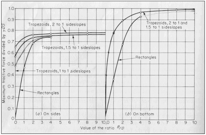
For very wide channels (B/D > 10), (1) is very representative of the shearing force felt on the bed. Because o is the average tractive force over the wetted area, the shear distribution becomes more non-uniform as the channel becomes narrower and more trapezoidal. As a result, the maximum tractive force is actually less than that predicted by (1) by some reduction factor. In addition, the channel walls, due to their inclination, have an even greater reduction effect on the maximum tractive force felt on the side slopes. For typical trapezoidal sections, it has been determined experimentally by Lane (1953) that the adjustment factor for both the bed and side slopes is largely dependent on the width to depth ratio and the side slope angle. The figure below presents the curves used to determine the adjustment factors for both the bed and side slopes.
The channel is considered stable if the tractive force at any given location in the cross section is less than the critical shear force. There are currently three methods for determining the critical shear stress in HEC-RAS. They are the Lane, Shields, and user-entered methods.
Lane Method:
Lane conducted experiments on canals in the San Luis Valley of Colorado to develop a method for predicting the critical shear stress. The canals tested were stable, straight, and regular in section, with a wide range of coarse particle sizes from about 0.3 inches to 3 inches in diameter. The results 
indicated that the critical shear stress was more or less linearly related to the diameter of the particle as follows:
| 2) | \tau _{cr} =0.4d_{75} |
The particle size, d_{75}(inches) was used because Lane noticed that throughout the experiments, the smaller particles were consistently shielded by the larger ones. By using a particle size in which only 25% of the particles were larger by weight, the initiation of motion was better represented.
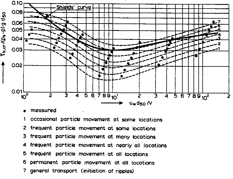
The Shields method has historically been much more widely used to determine the initiation of motion. Shields (1936) developed a relationship between the shear Reynolds number, Re* and the critical mobility parameter, θcr from a wide range of experimental data. Shield's diagram is presented in the figure below. The Shear Reynolds number is a representation of the ratio of inertial forces to viscous forces at the bed and is given as:
| 3) | \displaystyle Re_* = \frac{u_*d}{\nu} |
| Symbol | Description | Units |
|---|---|---|
u_* | Shear velocity, which is a representation of the intensity of turbulent fluctuations in the boundary layer. | |
d | Representative particle size (d50 is used in HEC-RAS) | |
\nu | Kinematic viscosity |
Where:
| 4) | u_* = \sqrt{gDS} |
| Symbol | Description | Units |
|---|---|---|
D | Water depth | |
S | Channel slope |
The critical mobility parameter is also known as the dimensionless shear stress and is given as:
| 5) | \displaystyle \theta _{cr} = \frac{\tau _{cr}}{(\gamma _s - \gamma ) d} |
| Symbol | Description | Units |
|---|---|---|
\gamma _s | Unit weight of the particles | |
\gamma | Unit weight of water |
From reviewing Shield's diagram, a number of things become clear. First, it is evident that the critical mobility parameter never drops below about 0.03. If the specific gravity of the sediments and the unit weight of water are assumed to be 2.65 and 62.4 lb/ft3, respectively, then the critical shear stress in lb/ft2 is never less than about 3 times the particle diameter (in feet). Also, if the shear Reynolds number exceeds about 450, the viscous forces in the sublayer no 
longer have an effect on the shearing force and the Shield's curve levels off with a critical mobility parameter of about 0.055. At this point, the critical shear stress is purely a function of the particle characteristics (size, weight). Likewise, when the shear Reynolds number drops below about 2.0, the inertial forces in the sublayer are negligible and the critical shear stress becomes linearly related to the particle characteristics and the inverse of the viscosity. However, in most natural stream conditions, the shear Reynolds number is high and inertial forces are dominant. HEC-RAS, however, will solve for the critical mobility parameter throughout the full range of Shield's diagram.
A third solution option provided in HEC-RAS allows the user to enter in a value for the critical mobility parameter. This option is given due to the wide range of research on initiation of motion and the varying definitions of what exactly initiation of motion means. Although the Shield's curve is meant to represent the initiation of motion, more recent research indicates that this curve more accurately represents permanent grain movement at all locations of the bed. This can be quite different from the shearing required to initiate motion of one or a few particles. The figure below presents the Shield's curve overlain on seven qualitative curves developed by Delft Hydraulics (1972) describing particle movement. It is evident that the critical shear stress found with Shield's curve can be as much as twice the value required to cause occasional particle movement at some locations.

Because of the variety of opinions on this matter, the user is able to supply HEC-RAS with his/her own value for the critical mobility parameter. This value should be selected such that it represents not only the type of conditions present, but also the type of results desired (i.e. is the design based on permanent particle movement, infrequent particle movement, no particle movement, total suspension, etc?). Many curves present the critical shear stress as the dependent parameter in the initiation of motion curves. A collection of these types of curves is shown in the figure below.
Note
It is important for the user to know that the value entered into RAS must be in the form of the Critical Mobility Parameter, or dimensionless shear stress shown as (5).
In HEC-RAS, a reduction factor is applied to the critical shear stress on the side slopes to account for the greater effect of gravity on the particle stability.
| 6) | \tau _{cr,s} = k_{\alpha} \tau _{cr} |
| Symbol | Description | Units |
|---|---|---|
\tau _{cr,s} | Critical shear stress on the side slope | |
\tau _{cr} | Critical shear stress on the bed | |
k_{\alpha} | Reduction factor |
Where:
| 7) | \displaystyle k_{\alpha} = cos \alpha \sqrt{1- \frac{tan^2 \alpha}{tan^2 \phi}} |
| Symbol | Description |
|---|---|
\alpha | Angle of the side slope, in degrees |
\phi | Angle of repose of the sediment, in degrees |
\phi > \alpha |
The angle of repose of the sediment particles must be entered by the user for the bed and both of the side slopes. Lane provides a diagram that suggests values for angles of repose for different grain sizes and angularities (see figure below and here).
HEC-RAS allows the user to solve for two dependent variables when two others are provided. The computations equate the critical shear stress with the actual shear stress to solve the first variable and then uses Manning's equation to solve the second variable. If the particle size is to be computed by HEC-RAS, one or all of the particle sizes (bed, left side slope, or right side slope) can be solved for, along with one other variable (depth, slope, or width). The equation RAS uses to determine the two unknown variables depends on the two unknown variables selected. Particle size is always determined using tractive force (i.e. equating critical shear with actual shear). The following table (Table 12-5) indicates which variable is solved by which method. This is helpful to know, in order to make sense of the results. 
For example, assume depth and width are to be solved for. If a large diameter grain size is used, a high value for allowable depth will be returned by the tractive force equations. Then because this depth is high, Manning's equation will return a very low value for width, sometimes unrealistic. Be aware that the value for width is the value to achieve uniform flow based on the maximum allowable depth for a stable cross section. The variables "width" and "maximum depth" in the above statement can be replaced with any of the four dependent variables in accordance with the equation priorities as shown in Table 12-5. 
The result of this solution technique can create an apparent inconsistency that the user must be aware of. If width and slope are solved for, slope will be determined by tractive force and width will be determined by Mannings. Now if the resulting width is used to solve for slope and particle size, the particle size will be different from what was used in the first solution. This is because when particle size and slope are solved for, particle size is first solved for using tractive force, then slope is solved using Mannings. Because true uniform flow conditions are rarely found on river reaches, be sure that the tractive force method is the equation solving the variable you are most interested in.
For more information on all three stable channel design methods presented herein, refer to the referenced literature.
Table 12-5 Solution Priorities for Tractive Force Method
Unknown Variables | Tractive Force | Mannings |
|---|---|---|
d, D | Min d | D |
d, B | Min d | B |
d, S | Min d | S |
D, B | Max D | B |
D, S | Max D | S |
B, S | Max S | B |
Where:
d = particle size (d50 for Shields, d75 for Lane)
D = Depth
B = Width
S = Slope